Stiffness analysis of a connection with a custom cross-section (EN)
1 New project
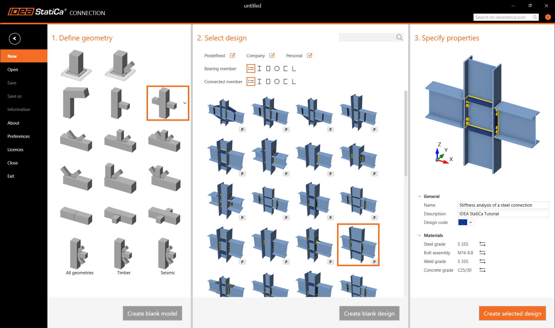
Launch IDEA StatiCa (download the newest version) and select the Connection application.
Create a new project by selecting the starting template from wizard closest to the desired design. Fill in the name, select the steel grade S355, design code Eurocode, and Create project.
2 Geometry
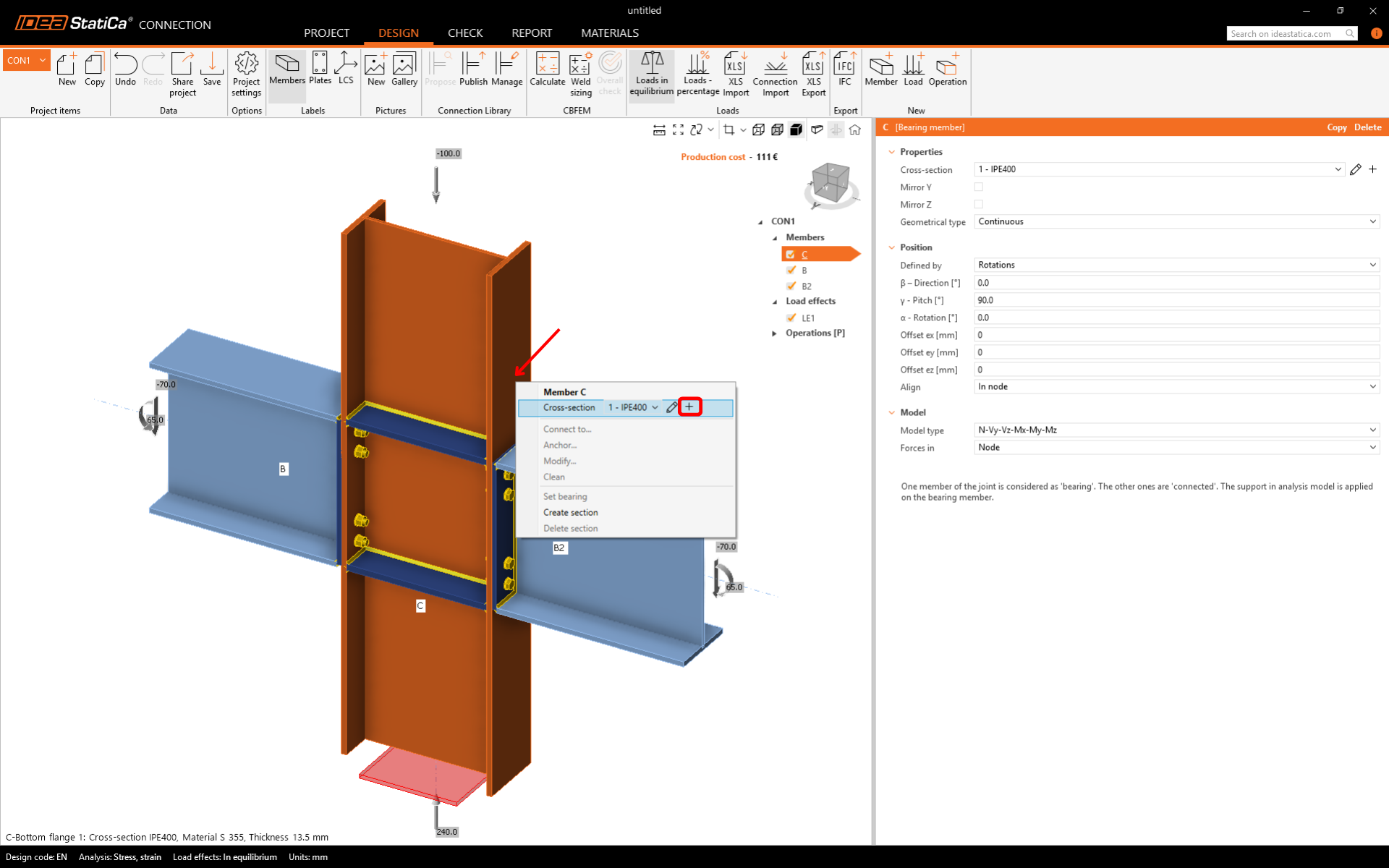
We will start with a definition of the custom cross-section built-up of three different sections.
Right-click on the vertical member C and open the context menu with available actions. Use the Plus button to add a new cross-section.
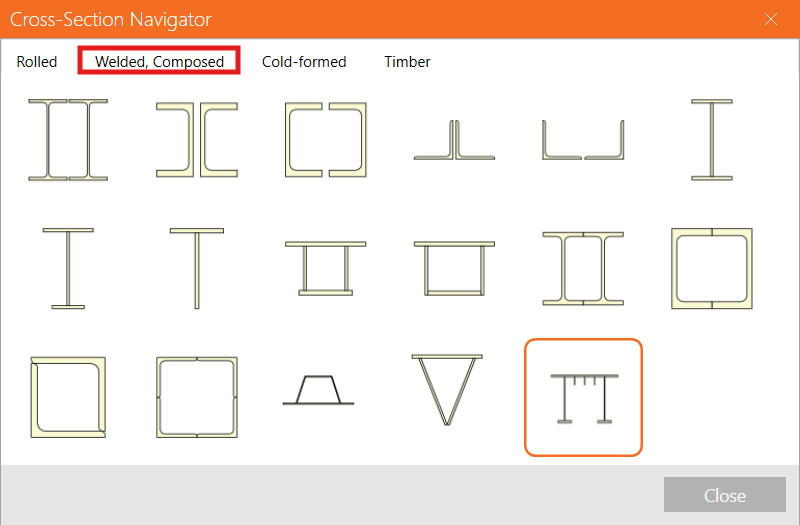
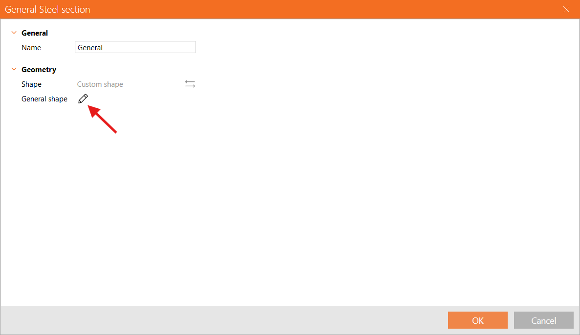
Go to the tab Welded, Composed, and select the General steel cross-section to add a user-defined shape.
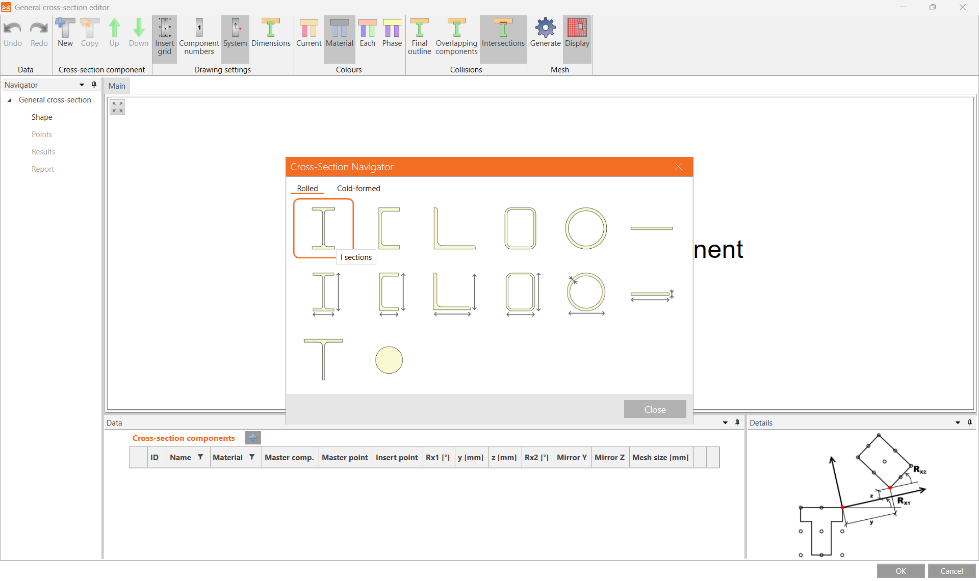
In the Cross-section editor, start by adding a new I-section.
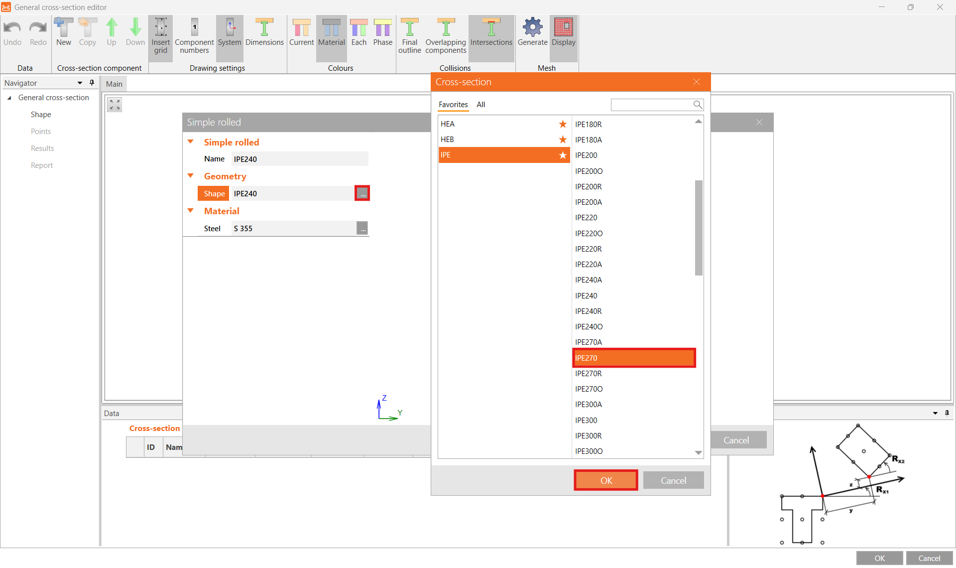
And switch the preselected profile to IPE270.
Then click New to add another section and select Sections T (I-cut).
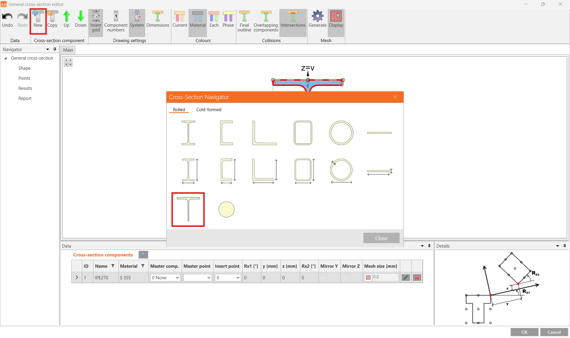
For the Shape select IPE270 from the cross-section library and input 120 mm for the Height and confirm OK.
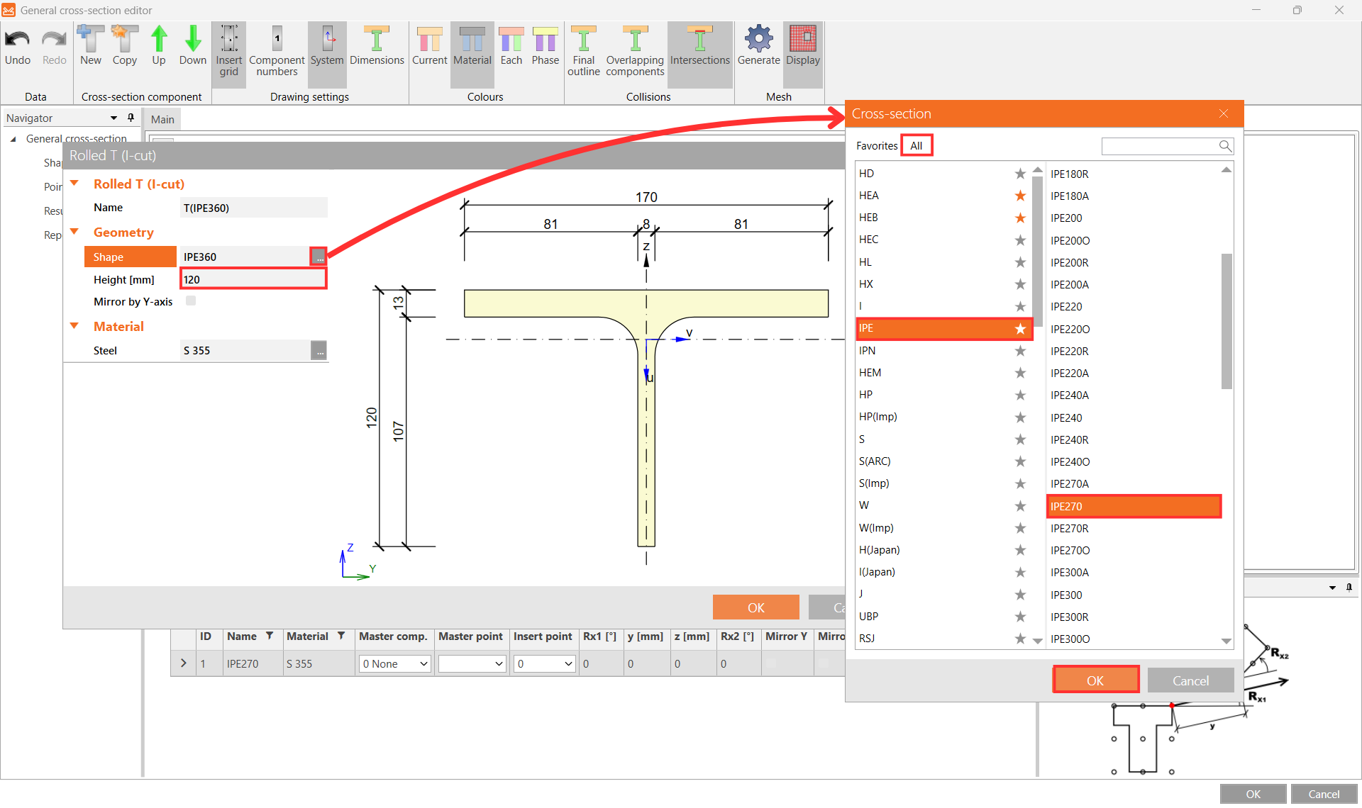
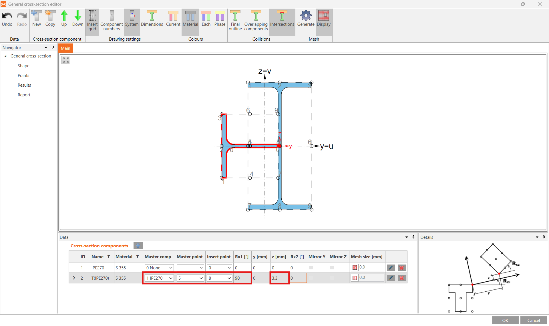
Now position the T section by selecting the proper Master component, Master point and Insert point and input rotation Rx1 of 90° and shift in the z direction of 3.3 mm.
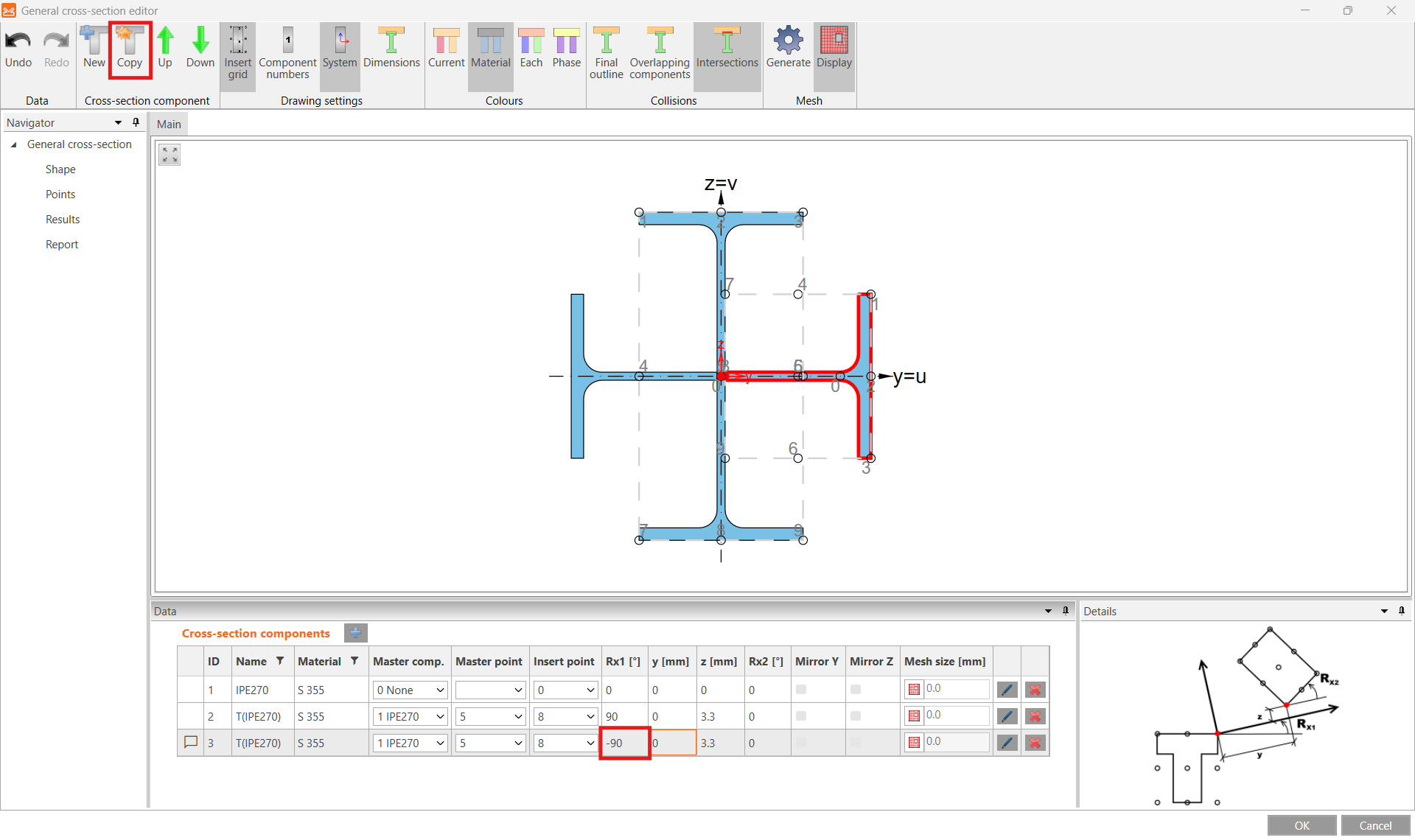
Make a Copy of this section part, edit the rotation Rx1 to -90°, and close the editor with the OK button.
More about the general cross-section editor in the article How to create and use a custom cross-section.
3 Load effects
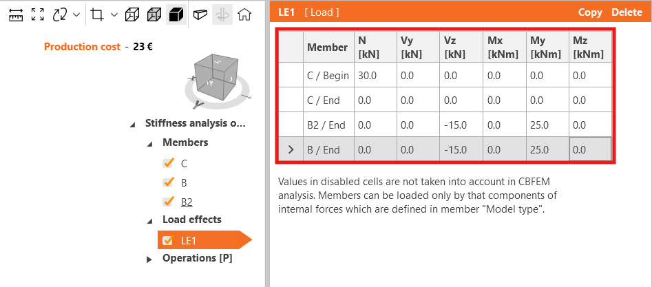
Adjust the values of the load effect LE1 accordingly.
4 Design
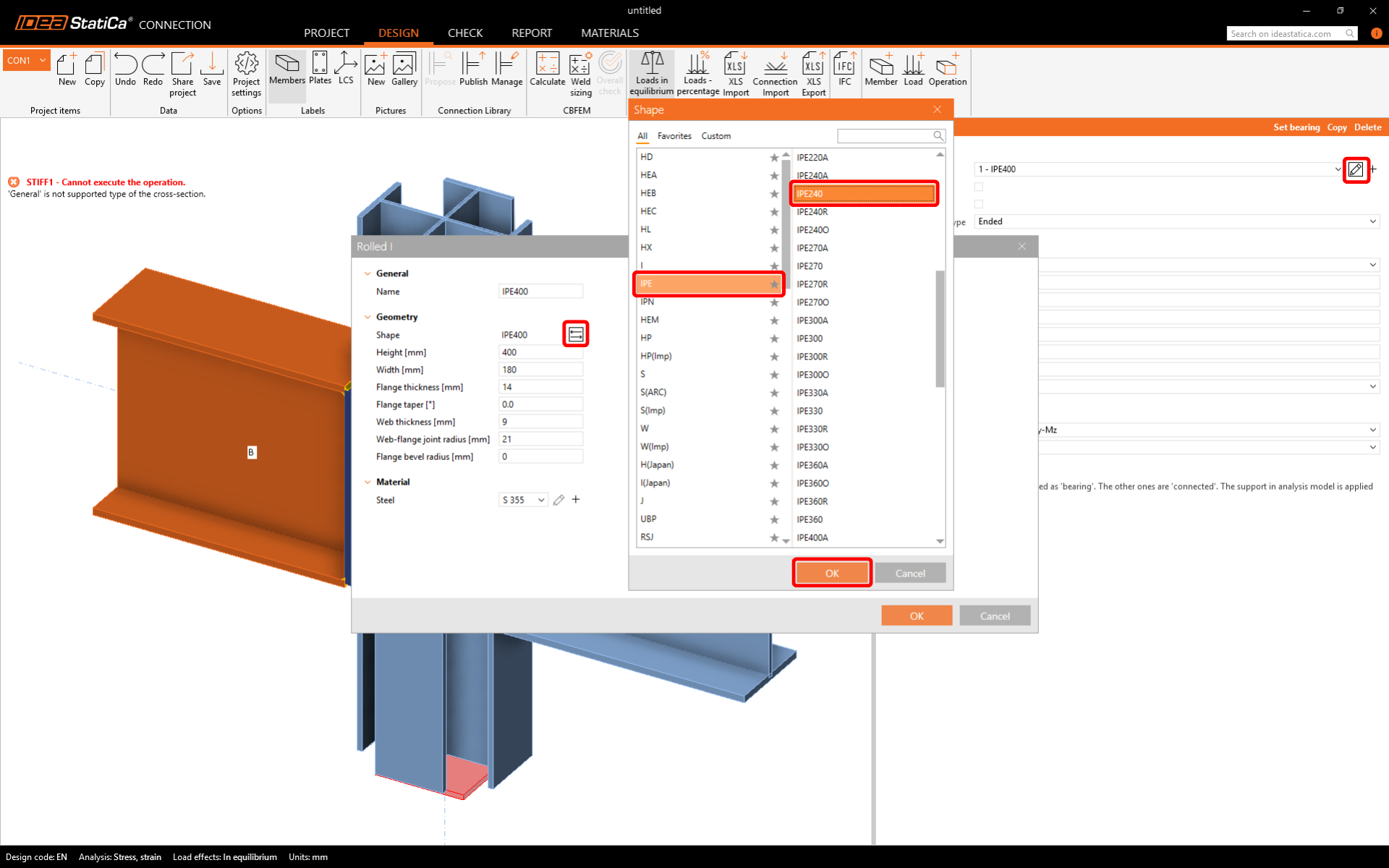
Set connected beams to a profile IPE240.
Adjust the parameters of Operations, turn off stiffeners.

5 Calculation and Check
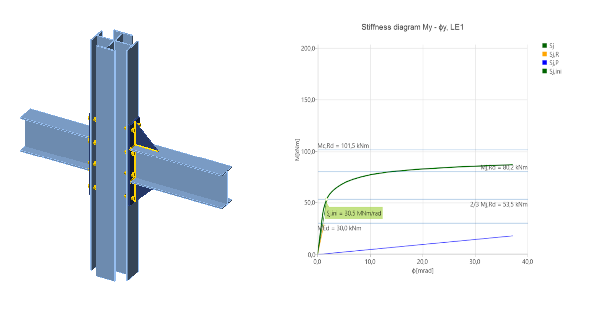
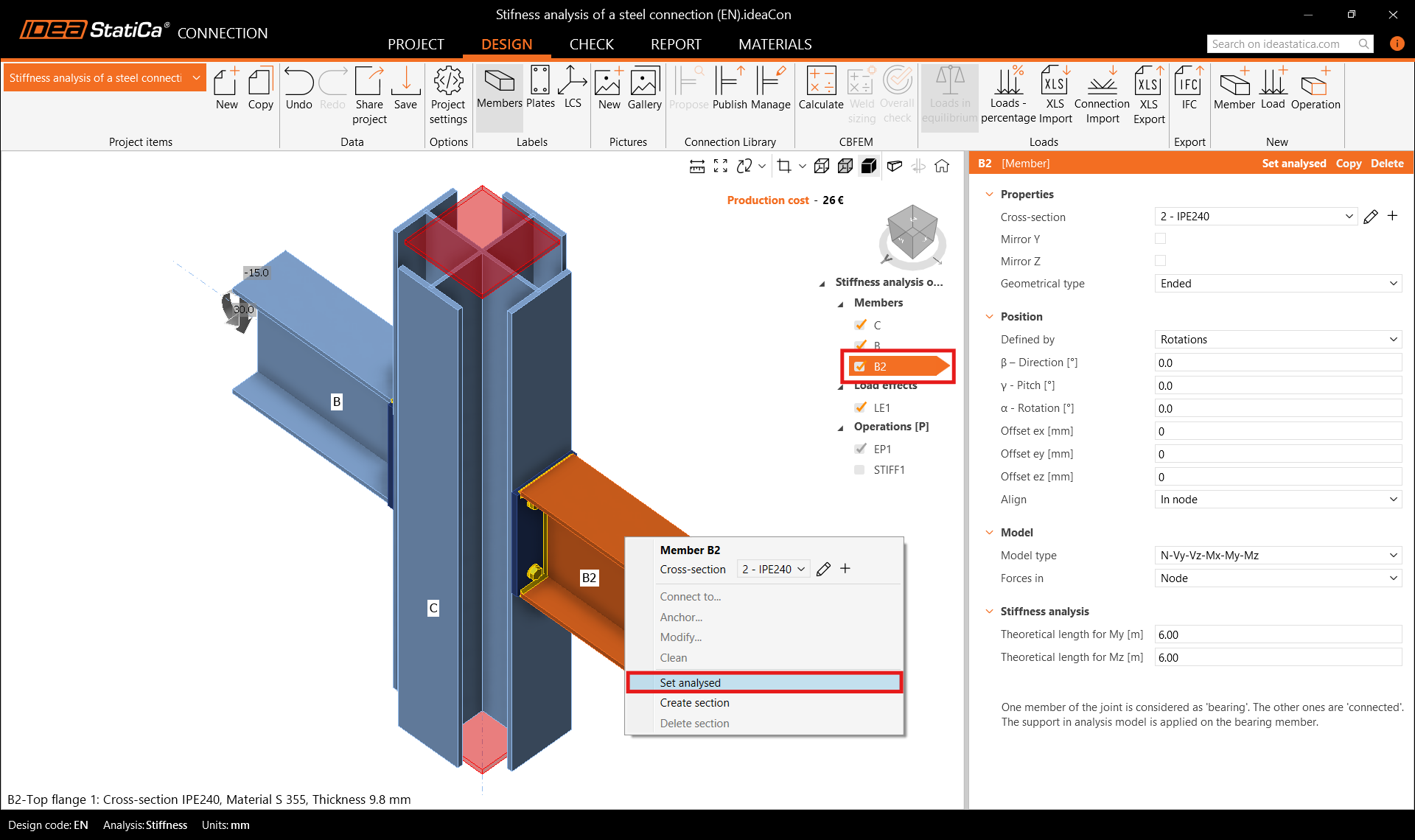
Select the project item CON1 and switch the analysis type to Stiffness analysis (ST).

Check that member B2 is set as the Analysed member (underlined in the list of members and displayed in member properties) or set it analyzed member via the right-click menu. Then run the Calculation.
Go to the tab Check and turn on the Plastic strain, Bolt forces, Mesh and Deformed to see the behavior of the connection. In the tab Rotational stiffness we can read the class as Semi-rigid and the value of the Initial rotational stiffness Sj,ini.

Note: For further understanding of the “Theoretical length for My, Mz” and the results, see the Stiffness analysis article and the Theoretical Background chapter Stiffness analysis and deformation capacity of steel joints.
6 Optimization of the connection
Go back to the tab Design to optimize the connection to achieve rigid connection.

Click on Operations and Explode the template to separate operations (EP1 and STIFF1).
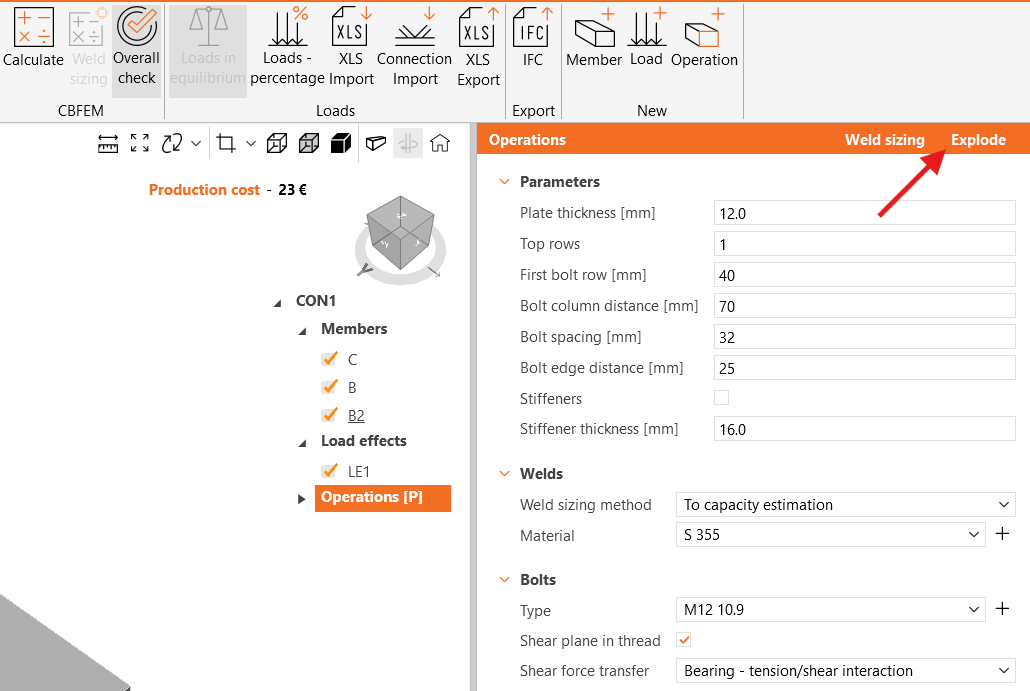
Make sure that the stiffener operation is deactivated, and adjust thickness, dimensions and position of bolts of the end plate EP1.

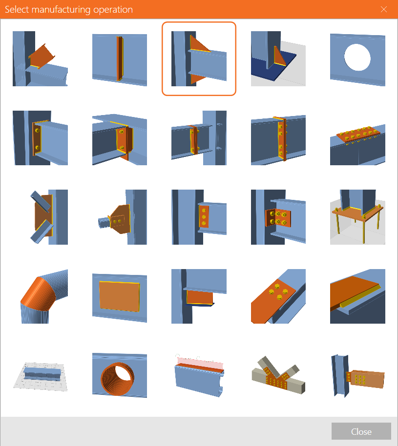
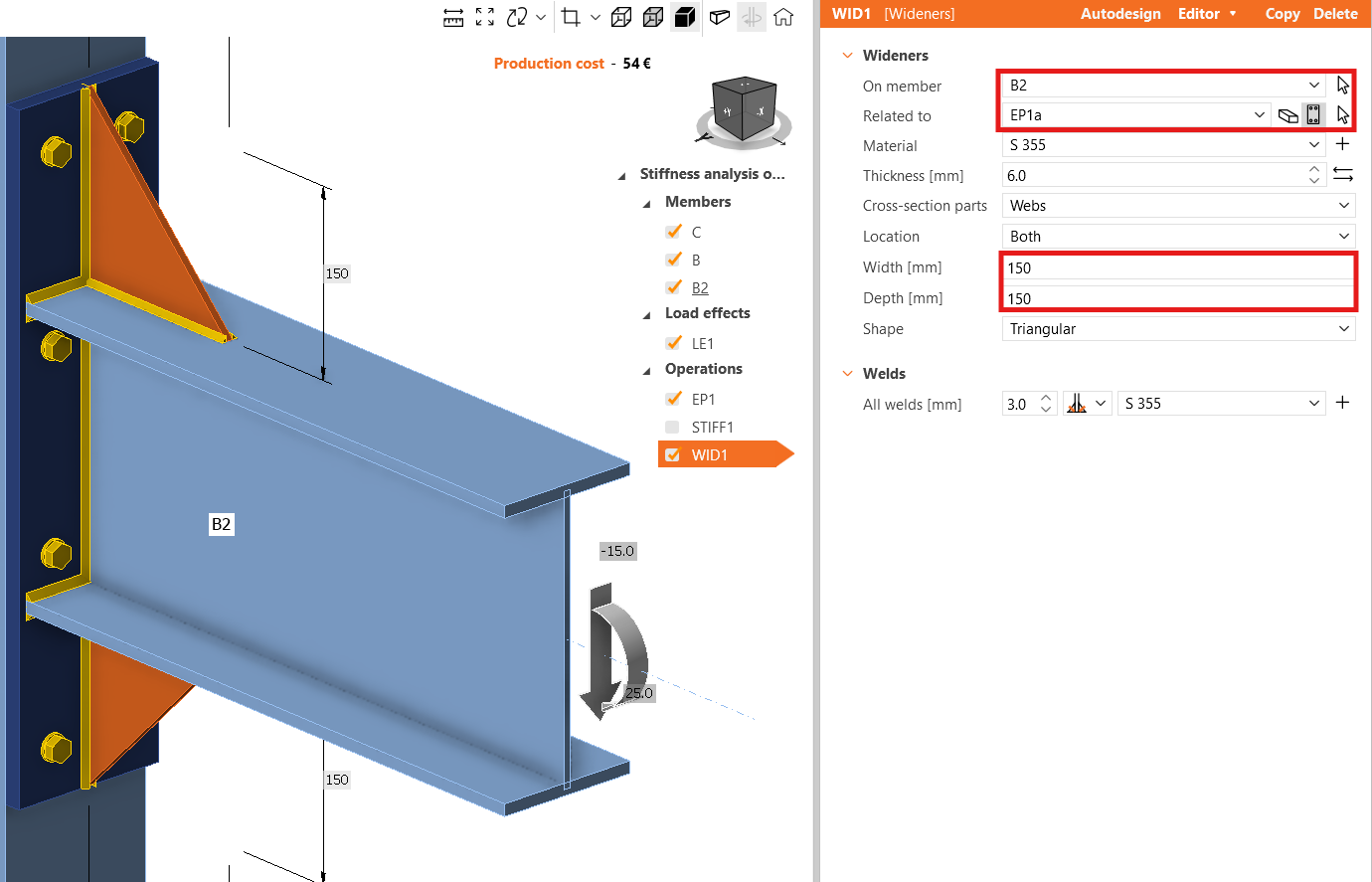
And add a new operation Widener.
Switch the Related to item to Plate (plate EP1a is selected automatically), and input 150 mm for both Width and Depth.
Calculate the stiffness analysis again, and in the Check tab see the class became Rigid and the higher value of the Initial rotational stiffness Sj,ini.

7 Report
As the last step, go to the tab Report. IDEA StatiCa offers a fully customizable report to print out or save in an editable format.

You have designed and code-checked a structural steel joint according to Eurocode (EN).
8 Explanation videos
For more information read the Theoretical background.