Precompressione in Detail - Tendini in post-tensione
Introduzione e presupposti
Innanzitutto, iniziamo con una breve descrizione del nostro software di progettazione del calcestruzzo. Questo articolo riguarda principalmente la progettazione del calcestruzzo precompresso nell'applicazione Detail, che è generalmente sviluppata per la progettazione di regioni di discontinuità o per la progettazione di elementi contenenti regioni di discontinuità, come aperture, estremità tagliate, ecc.
Per confrontare i risultati, utilizzeremo l'applicazione Beam il cui scopo, come si può intuire dal nome, è la progettazione di travi in calcestruzzo.
In secondo luogo, è necessario definire alcune ipotesi e restrizioni per comprendere meglio la progettazione di travi in cemento armato precompresso in dettaglio.
- L'analisi in funzione del tempo (TDA) non è implementata nell'applicazione Detail. Per contro, la TDA è implementata nell'applicazione Beam per la progettazione di travi in cemento armato precompresso.
- La TDA può essere simulata in Detail utilizzando il coefficiente di scorrimento e gli incrementi.
- I carichi di ritiro e di temperatura non sono implementati nel Dettaglio.
- Il calcestruzzo in tensione nel Dettaglio è escluso. Quindi, per il nostro confronto, dobbiamo avere una trave senza fessure. Naturalmente, lo stesso approccio può essere utilizzato in generale per le travi affette da fessure, ma i risultati non saranno gli stessi nella Trave perché in essa è previsto solo il calcolo lineare.
Incrementi
Prima di passare all'esempio, è necessario capire come funzionano gli incrementi per la progettazione del calcestruzzo precompresso nel Dettaglio.
Ci sono 3 tipi di carico che vengono applicati al modello in tre incrementi nell'applicazione Detail.
- precompressione - per l'incremento P
- Permanente - per l'incremento G
- Variabile - per l'incremento V
Se si crea una combinazione contenente casi di carico di tutti i tipi di carico, l'intera porzione del tipo di carico Precompressione sarà applicata al primo incremento P, l'intera porzione del tipo di carico Permanenti sarà applicata al secondo incremento G e l'intera porzione del tipo di carico Variable sarà applicata al terzo incremento V.
Il motivo per cui ci sono incrementi è che per i calcoli SLE vengono utilizzati diversi modelli di materiale (diversi moduli di elasticità), per SLU c'è un solo modello di materiale definito in Material model (EN).

Come si può vedere, ci sono tre moduli di elasticità:
- Ec,eff,press =Ecm / (1+φpress) - Modulo di elasticità effettivo del calcestruzzo per l'incremento di P
- Ec,eff,perm =Ecm / (1+φperm) - Modulo di elasticità effettivo del calcestruzzo per l'incremento G
- Ecm - Modulo di elasticità secante del calcestruzzo
Dove φpress e φperm sono i coefficienti di scorrimento per gli incrementi P e G. I coefficienti possono essere impostati in Materiali e modelli.
Si noti che per gli effetti a breve termine si utilizza solo Ecm . È valido per tutti e tre gli incrementi. La perdita a lungo termine viene presa in considerazione solo per gli effetti a lungo termine.
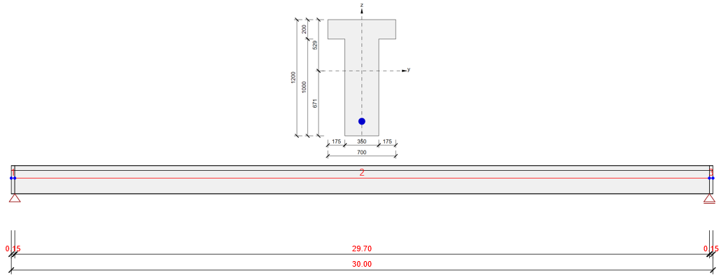
I parametri della trave
Due modelli identici sono creati nelle applicazioni Beam e Detail. Sono allegati alla fine di questo articolo. Scaricateli e consultarli durante la lettura dell'articolo.
L'esempio di una trave in calcestruzzo verrà presentato nell'applicazione Beam e successivamente verrà effettuato il confronto con l'applicazione Detail per tre fasi costruttive.
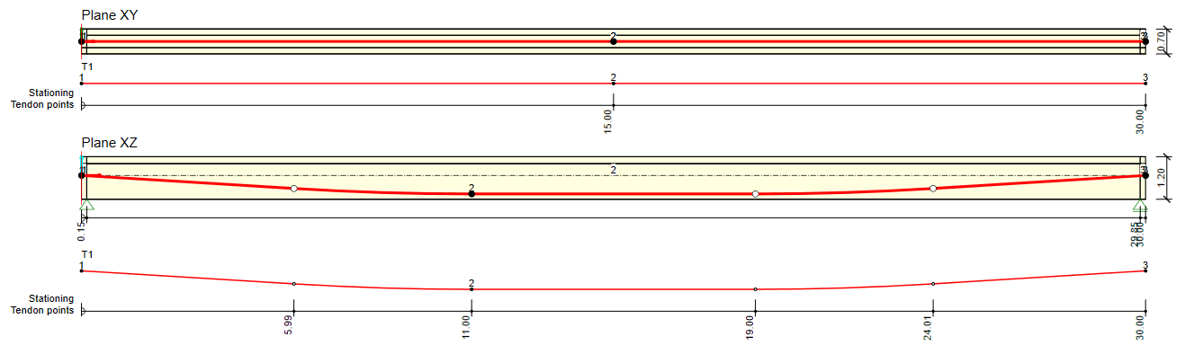
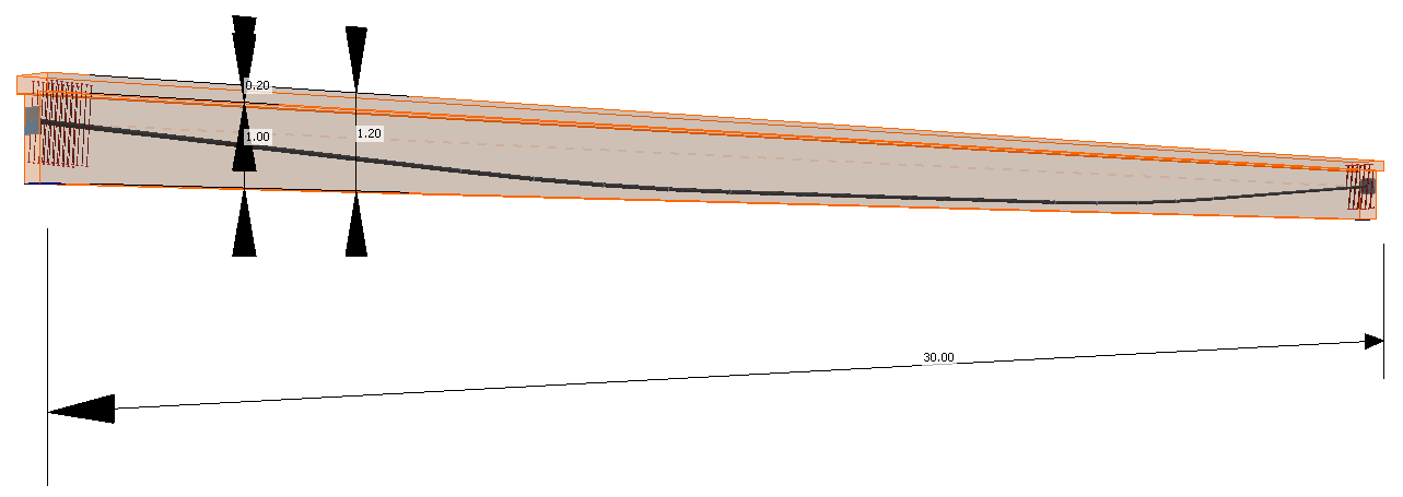
L'esempio è una trave semplice a campata singola con sezione trasversale a T in calcestruzzo C50/60 precompressa da un tendine in post-tensione a 19 trefoli.
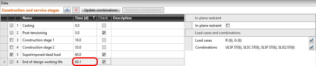
Verificheremo la trave in tre fasi costruttive.
- Trasferimento della precompressione - 5 d (subito dopo l'applicazione della precompressione)
- Carico permanente aggiuntivo - 60 d (inizio della vita utile)
- Fine della vita utile di progetto - 18250 d (50 anni)
Le altre fasi possono essere eseguite in modo analogo.
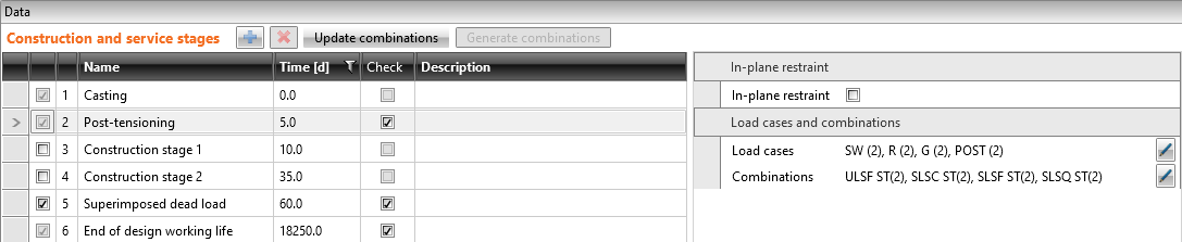
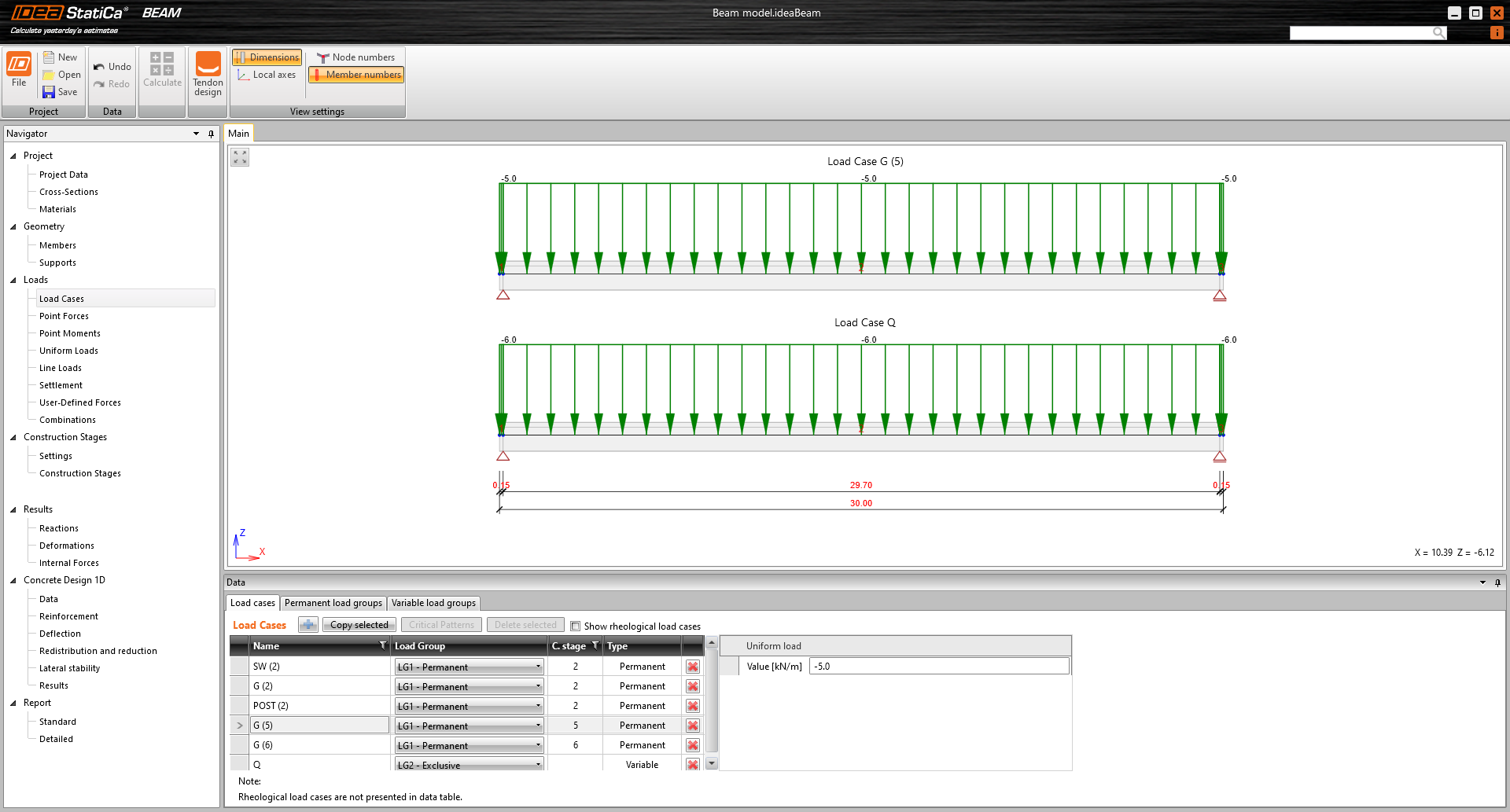
Sono inseriti solo quattro casi di carico. I numeri tra parentesi sono i numeri delle fasi costruttive in cui vengono applicati i singoli carichi.
- Peso proprio - SW (2)
- Precompressione - POST (2)
- Carico permanente - G (5)
- Carico variabile - Q
Gli altri casi di carico sono vuoti.
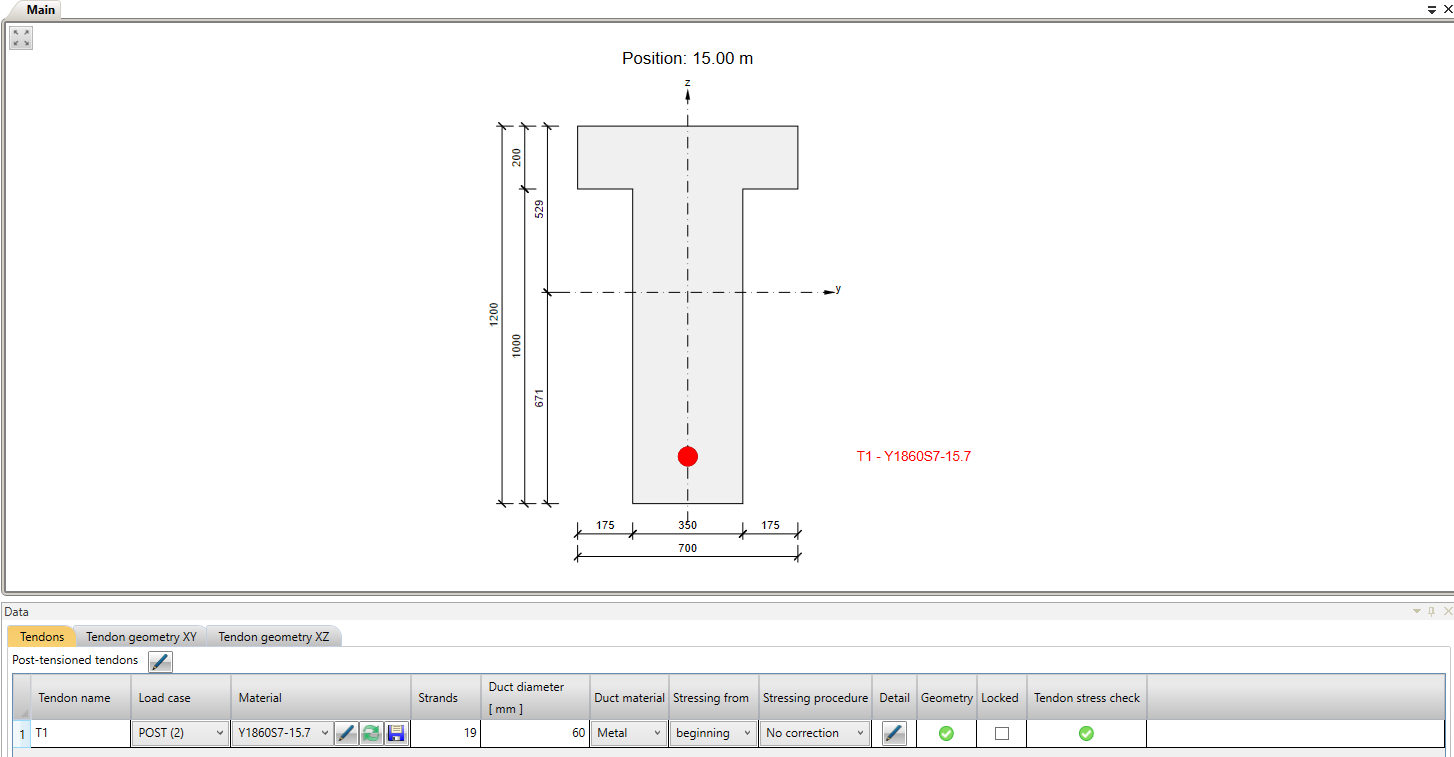
Ora esaminiamo la precompressione. È presente un tendine a 19 trefoli. Si noti il diametro del condotto. L'applicazione Beam tiene conto della sezione indebolita dal condotto. D'altra parte, l'applicazione Detail tiene conto della sezione intera. Pertanto, per ottenere la migliore corrispondenza possibile dei risultati, il diametro del condotto è stato impostato con il diametro più piccolo possibile nell'applicazione Beam.
Nella figura seguente è possibile vedere il grafico Tensione/Perdite del tendine.
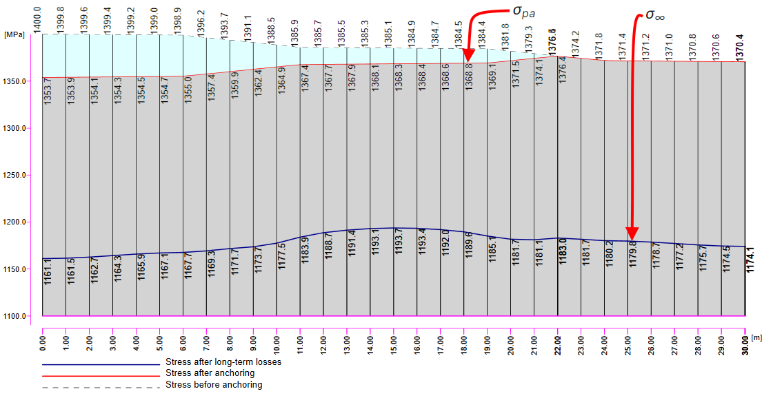
Esistono diversi valori di tensione nel tendine che devono essere controllati durante l'applicazione della precompressione. A questo punto, ci fermeremo e spiegheremo brevemente il processo di precompressione e le singole tensioni e perdite.
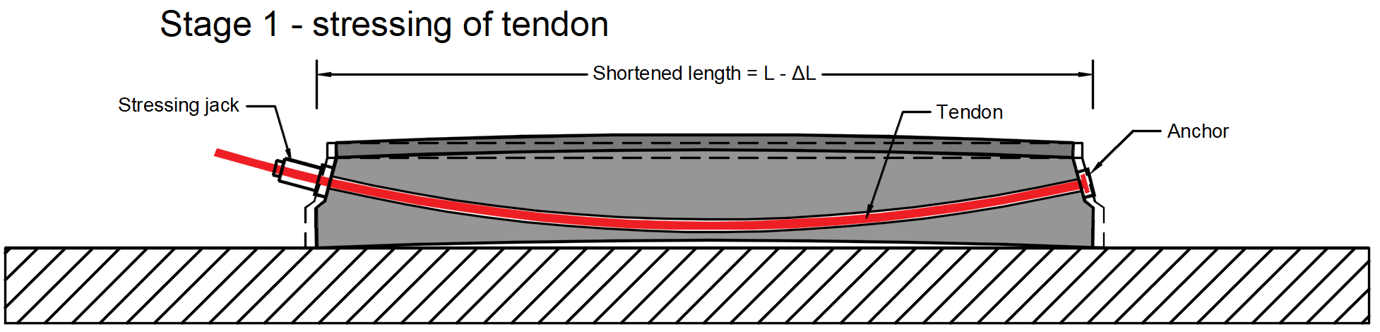
Processo di precompressione per trave in post-tensione
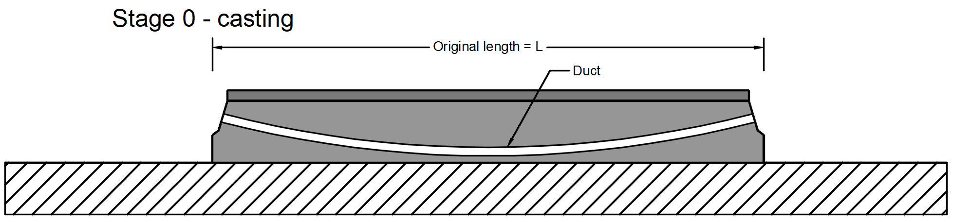
Fase 0 - getto -> L'elemento in calcestruzzo viene gettato contenente l'armatura e un condotto vuoto.
Fase 1 - messa in tensione del tendine -> Il tendine viene inserito nel condotto, ancorato su un lato e precompresso dal martinetto di tesatura sull'altro lato (oppure può essere teso in due fasi da entrambi i lati, ma non è il nostro caso). Durante il processo di tesatura, la trave si deforma. Pertanto vi è una tensione iniziale σp,ini al martinetto di tesatura, la tensione prima dell'ancoraggio nel tendine che è una tensione iniziale influenzata dalla perdita per attrito Δσpμ. Nel nostro esempio σp,ini = 1400 MPa.
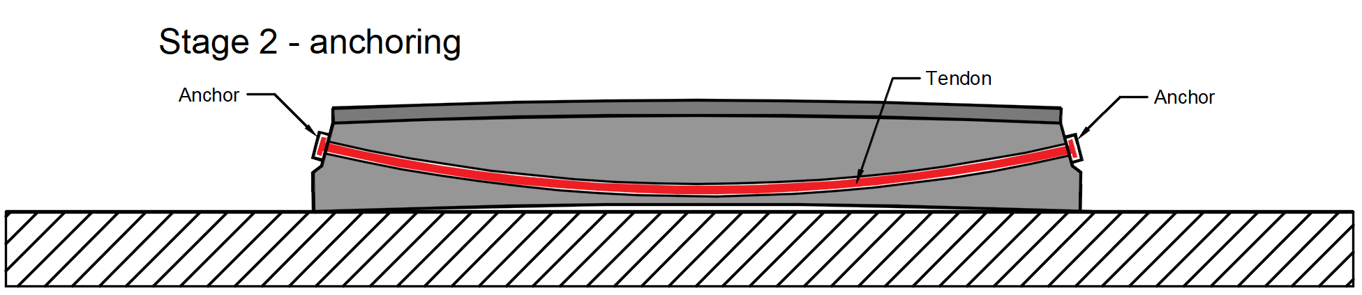
Fase 2 - ancoraggio -> L'estremità tesa viene ancorata e si verifica la perdita per scorrimento dell'ancoraggio (slip) Δσpw. Non vi è altra perdita dovuta alla deformazione elastica immediata del calcestruzzo, poiché tale deformazione si è realizzata prima dell'ancoraggio. La tensione dopo l'ancoraggio (dopo le perdite a breve termine) σpa sarà presente nel tendine al termine di questa fase.
Nel caso dei tendini in post-tensione, è possibile inserire l'effetto della precompressione in Detail in due modi.
- Le perdite a breve termine sono calcolate automaticamente - L'input è la tensione di ancoraggio (tensione iniziale) σp,ini. Le perdite Δσpμ e Δσpw sono calcolate automaticamente in base al set di ancoraggio, al coefficiente di attrito e alla variazione angolare non intenzionale, che sono anch'essi dati di input in questo caso.
- Le perdite a breve termine sono definite dall'utente - L'input è la tensione dopo l'ancoraggio (dopo le perdite a breve termine) σpa. Si inserisce il valore della tensione in ciascun vertice del tendine.
Si noti che in Detail il calcolo automatico delle perdite a breve termine non include la correzione della rilassazione. Anche questa è stata disattivata in Beam nel nostro esempio.
- Per saperne di più: Precompressione in Detail - Descrizione del modello
Fase di trasferimento della precompressione
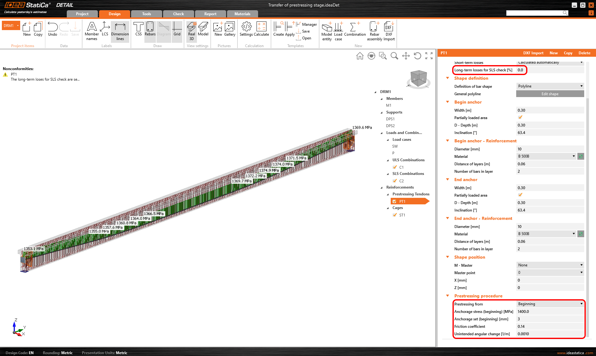
Il modello è definito, quindi passiamo all'applicazione Detail e vediamo come impostare la prima fase. Il modello è lo stesso, abbiamo solo aggiunto staffe per il trasferimento a taglio, ma ciò non influenzerà i risultati.
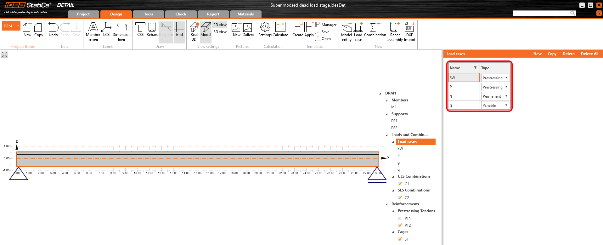
Per questa fase, ci sono solo due casi di carico:
- SW - tipo Precompressione (Peso proprio)
- P - tipo Precompressione (Precompressione)
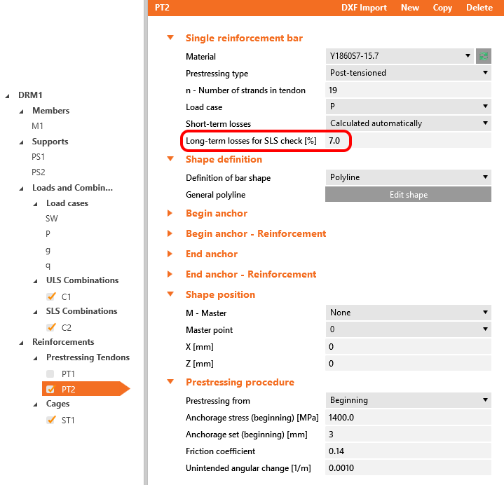
Entrambi verranno applicati nel primo incremento di carico. Le perdite a lungo termine per le verifiche SLE sono impostate a 0% e i valori per la procedura di precompressione sono inseriti allo stesso modo del modello nell'applicazione Beam. È inoltre possibile confrontare la tensione calcolata automaticamente dopo le perdite a breve termine σpa con il grafico Tensione/Perdite del tendine di Beam.
- Per saperne di più: Descrizione generale degli impulsi di carico nell'applicazione Detail
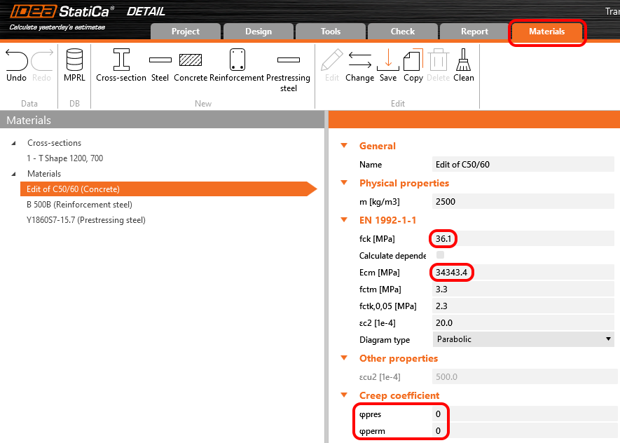
I coefficienti di viscosità sono anch'essi impostati a zero perché vogliamo valutare la fase subito dopo il trasferimento della precompressione. Si può anche notare che il valore di Ecm e fck è stato riscritto con i valori a 5 giorni inseriti in Beam.
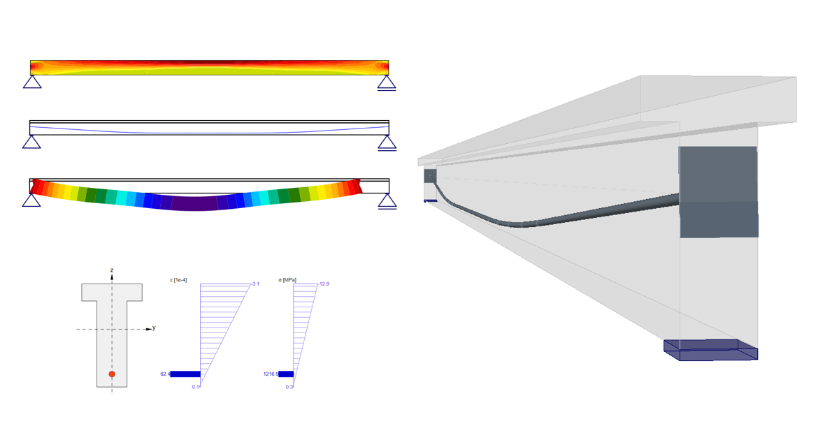
Confrontiamo quindi i risultati. In questo caso, gli effetti a lungo termine e a breve termine sono gli stessi, poiché non è stata inserita alcuna perdita a lungo termine.
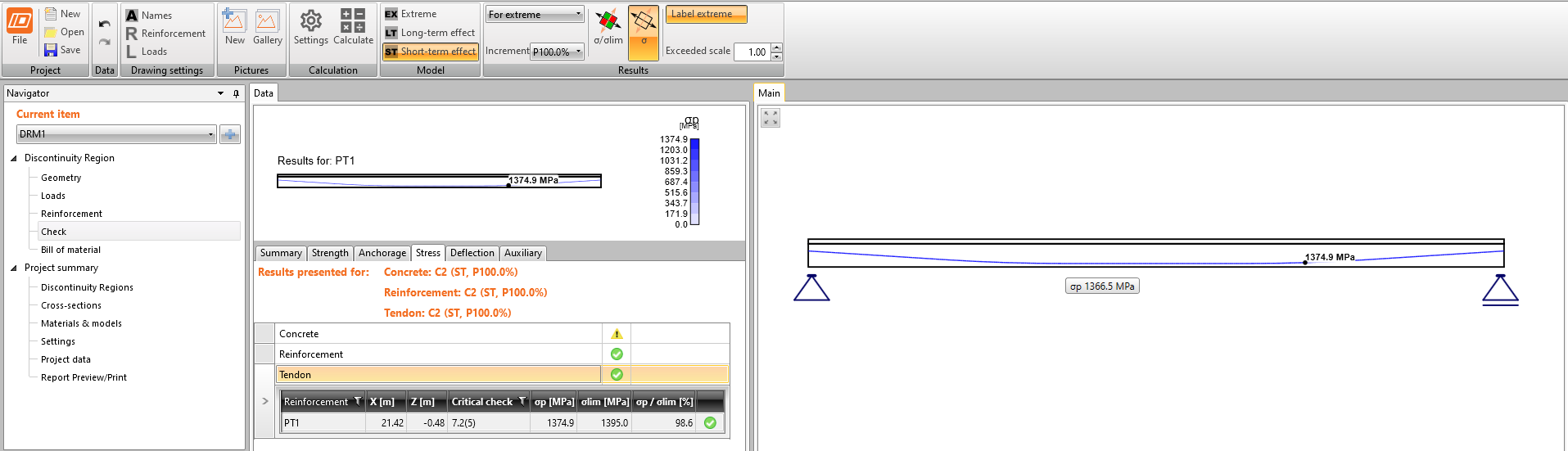
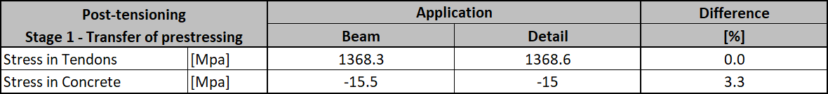
Tensione nei tendini in SLE - tensione dopo le perdite a breve termine σpa:
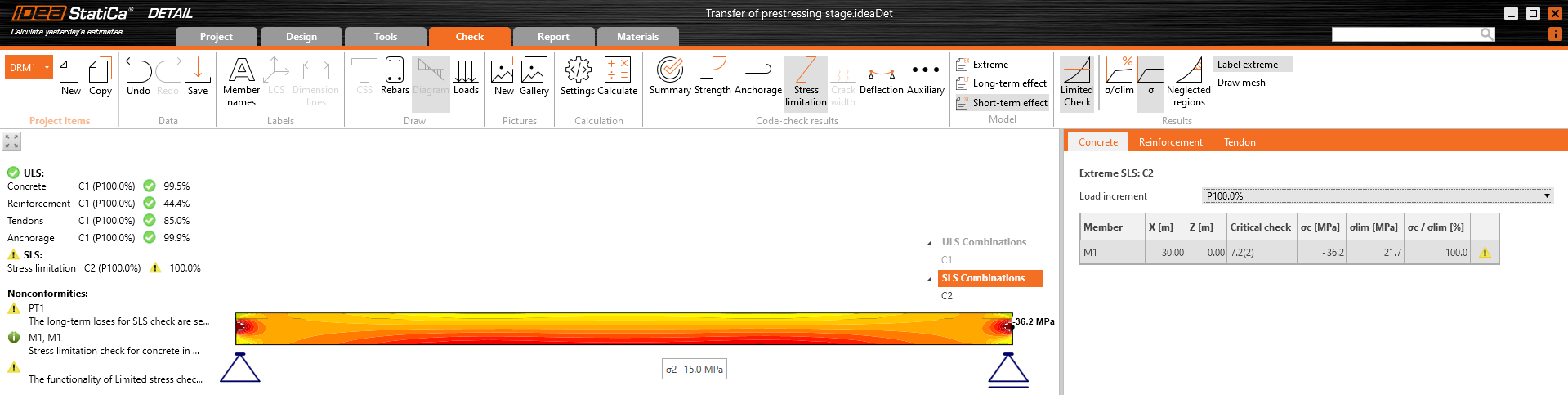
Tensione nel calcestruzzo in SLE:
- Per saperne di più: Descrizione generale dei risultati SLE nell'applicazione Detail
La verifica della sezione SLE da Beam:
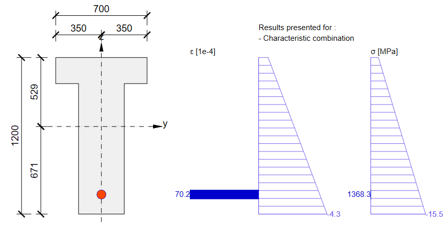
Come si può vedere, vi è una buona corrispondenza. Sembra quindi che l'input per questa fase sia stato eseguito correttamente. Si noti che i coefficienti rinf e rsup definiti in EN 1992-1-1; 5.10.9 (1) sono stati impostati come 1,0 in Beam.
Per lo SLU vi sarà una differenza maggiore. Ciò è dovuto a un approccio diverso utilizzato nell'applicazione Beam per determinare la risposta allo SLU. In questo caso, l'incremento aggiuntivo visibile nei risultati di Beam rappresenta tensioni non bilanciate. Si tratta di un argomento complesso completamente diverso. L'aspetto importante è che la capacità portante sarebbe quasi la stessa nelle applicazioni Detail e Beam.
- Per saperne di più: Descrizione generale dei risultati SLU nell'applicazione Detail
Ora sapete come utilizzare l'applicazione Detail per la progettazione di strutture in calcestruzzo precompresso con tendini in post-tensione per la fase di trasferimento della precompressione. È sufficiente modificare la geometria e aggiungere alcune discontinuità come aperture, ecc.
Fase di carico permanente aggiuntivo
Il tempo (età del calcestruzzo) per questa fase è di 60 giorni. Lo scopo di questa fase è verificare la trave in calcestruzzo all'inizio della sua vita utile, includendo i carichi permanenti e variabili. Vengono quindi aggiunti gli altri due casi di carico. Gli impulsi di carico sono naturalmente gli stessi del modello nell'applicazione Beam.
È necessario determinare due valori come input per Detail.
- Coefficiente di viscosità per il periodo da 2 a 60 giorni
- Stima delle perdite a lungo termine per il periodo da 2 a 60 giorni
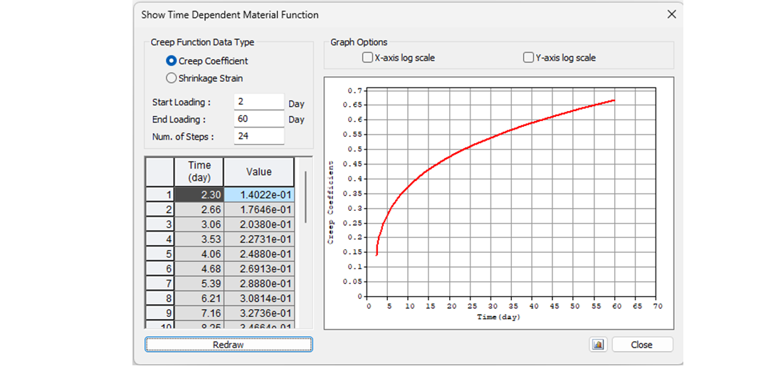
Iniziamo con il coefficiente di viscosità. Nella figura seguente è possibile vedere la funzione di viscosità da 2 a 60 giorni per la classe di calcestruzzo C50/60 e classe di cemento R secondo l'Eurocodice. Il valore del coefficiente di viscosità è quindi φpres ≈ φ(60) - φ(2) = 0,65 - 0,15 = 0,50
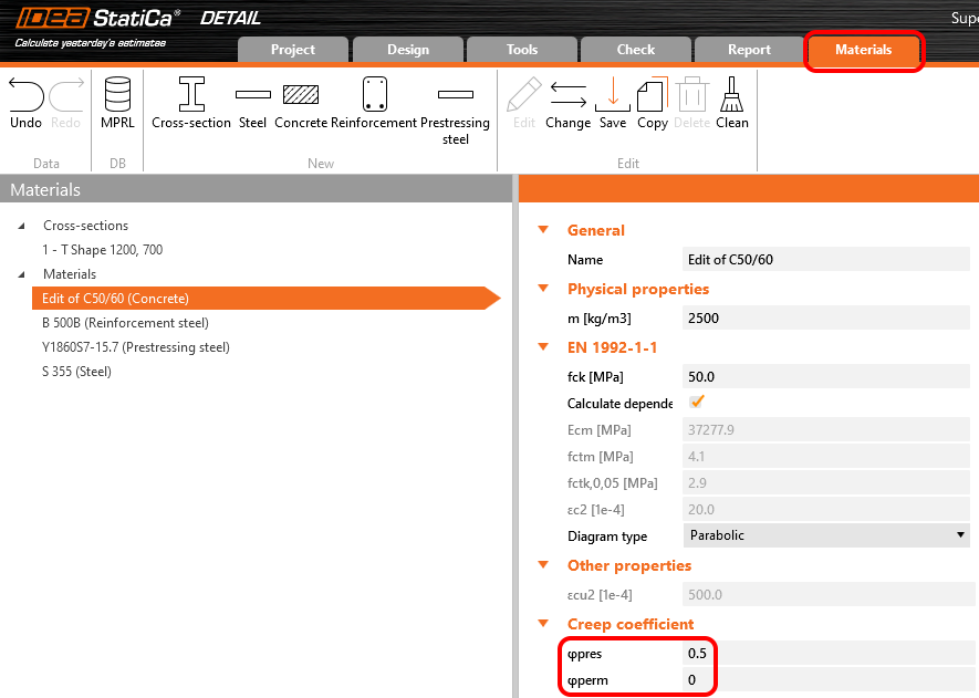
Nell'applicazione Detail, il coefficiente di viscosità può essere impostato in Materiali e modelli. È evidente che il modulo di elasticità deve essere impostato come valore predefinito Ecm (si ricordi il capitolo sugli Incrementi e il relativo grafico). Si può anche notare che il valore di φperm = 0,0, il che è dovuto al fatto che vogliamo applicare i carichi permanenti come carichi di breve durata, così come i carichi variabili.
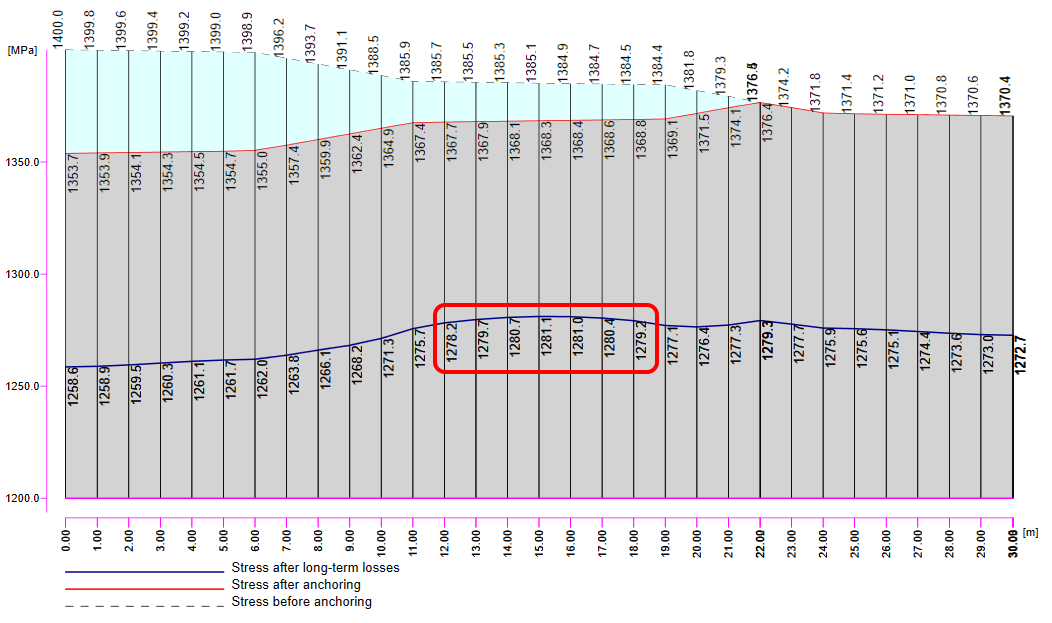
È ora il momento di considerare le perdite a lungo termine. Naturalmente, è possibile stimarle (la mia stima sarebbe dell'8%). È il modo più semplice, ma nel nostro esempio vogliamo farlo con precisione. Abbiamo quindi calcolato σ60 - Tensione dopo le perdite a lungo termine a 60 giorni (linea blu) nell'applicazione Beam impostando il tempo finale a 60 giorni.
Il valore di σ60 = 1280 MPa come si può vedere nella figura seguente (linea blu).
Dobbiamo quindi esaminare nuovamente il valore di σpa. Abbiamo già confermato che i valori sono gli stessi in Beam e Detail.
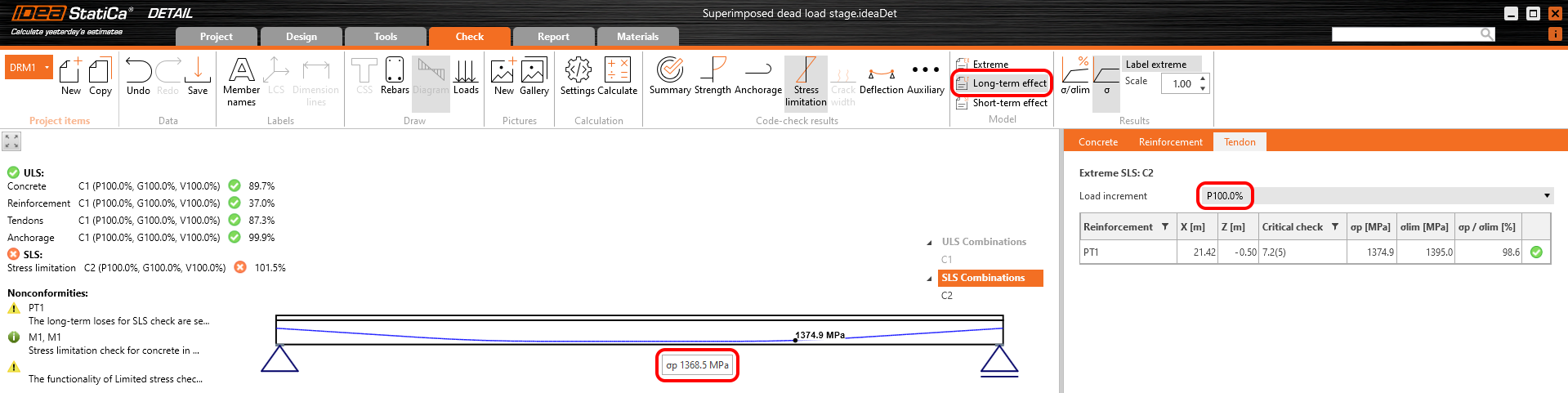
Nella figura possiamo vedere che σpa = 1368,6 MPa nella mezzeria della campata.
Le perdite a lungo termine possono quindi essere calcolate come σ60 / σpa = 1280 / 1368,6 = 0,93 -> la perdita a lungo termine è del 7%. Inseriamo il valore e confrontiamo i risultati.
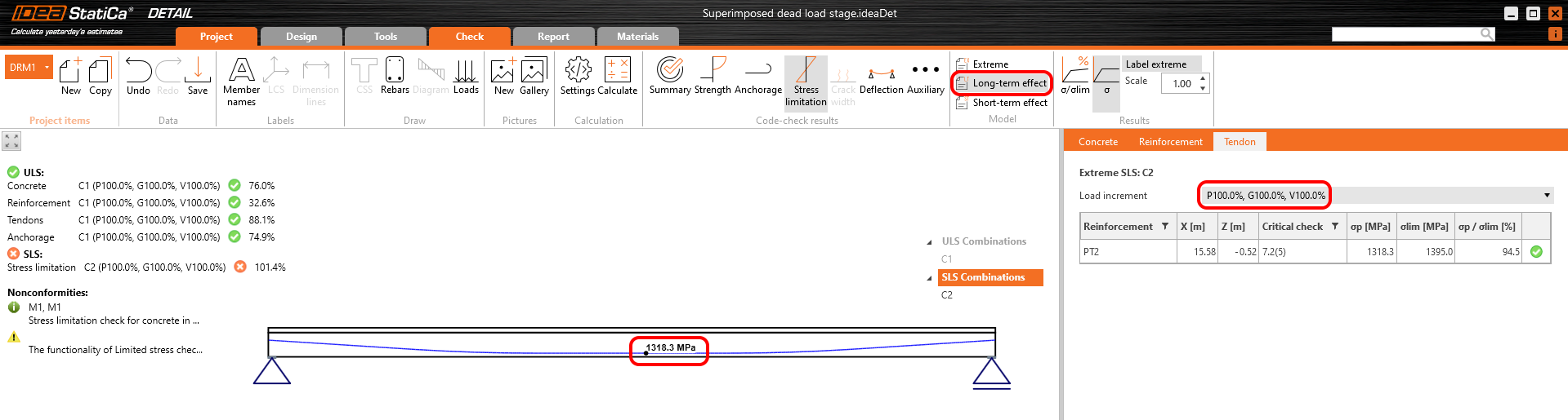
I risultati vengono letti per le perdite a lungo termine (vogliamo includere viscosità e perdite) e per tutti gli incrementi (vogliamo includere tutti i carichi).
Tensione nei tendini in SLE:
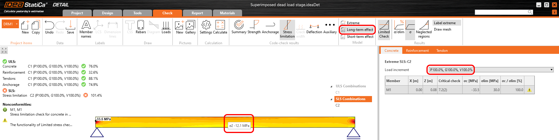
Tensione nel calcestruzzo in SLE:
La verifica della sezione SLE da Beam:
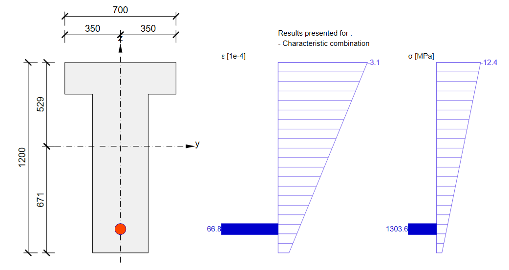
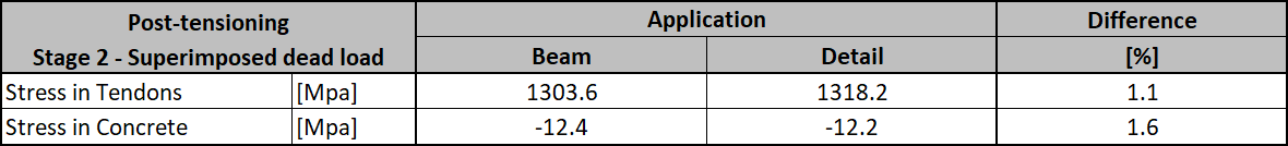
Anche in questo caso vi è una buona corrispondenza. Sembra quindi che l'input per questa fase sia stato eseguito correttamente. Per lo SLU si presenterà lo stesso problema descritto nella fase precedente. Si noti che i coefficienti rinf e rsup definiti in EN 1992-1-1; 5.10.9 (1) sono stati impostati come 1,0 nell'applicazione Beam.
Si ricordi ora l'inizio di questo articolo dove sono stati descritti gli incrementi. Nel modello dell'applicazione Detail per questa fase, è possibile esaminare i singoli incrementi per vedere l'influenza dei singoli casi di carico. È inoltre possibile verificare gli effetti a breve termine che differiranno dal precedente modello dell'applicazione Detail per la fase di trasferimento della precompressione. Il motivo è il diverso modulo di elasticità Ecm utilizzato in questi modelli.
Ciò che si può effettivamente vedere nel modello per la fase di carico permanente aggiuntivo negli effetti a breve termine è una fase di trasferimento della precompressione in cui t=28 giorni. Pertanto, se non è necessario precomprimere la trave prima di 28 giorni, non è necessario creare un modello speciale per la progettazione di travi in calcestruzzo precompresso nella fase di trasferimento della precompressione.
Fine della vita utile di progetto
L'approccio sarà lo stesso della fase precedente. Prima di tutto, è necessario determinare i coefficienti di viscosità. Nella figura seguente è possibile vedere la funzione del coefficiente di viscosità.
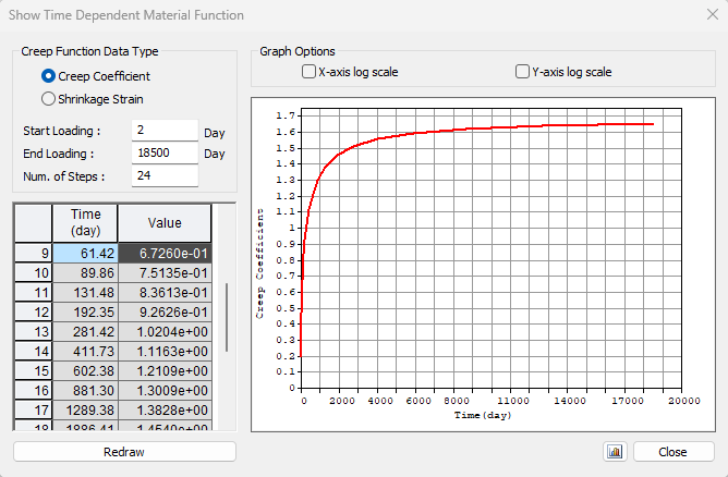
Il valore φpres ≈ 1,65 per il periodo da 2 a 18250 giorni per la classe di cemento R secondo l'Eurocodice. Il valore φperm = φ(18250) - φ(60) ≈ 1,65 - 0,65 = 1,00 per il periodo da 60 a 18250 giorni. Si noti il valore evidenziato φ(60) nella tabella precedente.
Dobbiamo quindi esaminare nuovamente il valore di σpa. Abbiamo già confermato che i valori sono gli stessi in Beam e Detail.
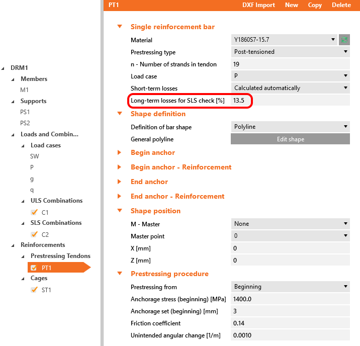
Le perdite a lungo termine possono essere calcolate come σ∞ / σpa = 1185 / 1368,6 = 0,865 -> la perdita a lungo termine è del 13,5%. Il valore di σ∞ è determinato nel capitolo I parametri della trave nel grafico Tensione/Perdite del tendine. Inseriamo il valore e confrontiamo i risultati.
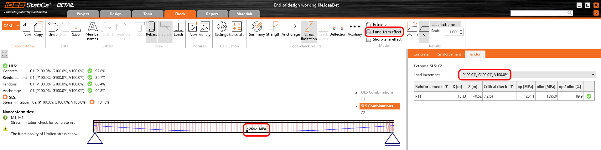
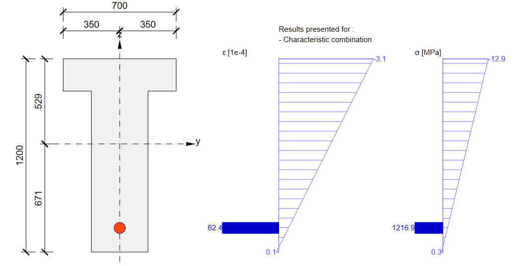
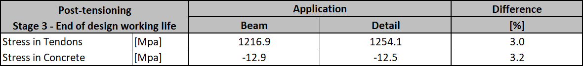
Tensione nei tendini in SLE:
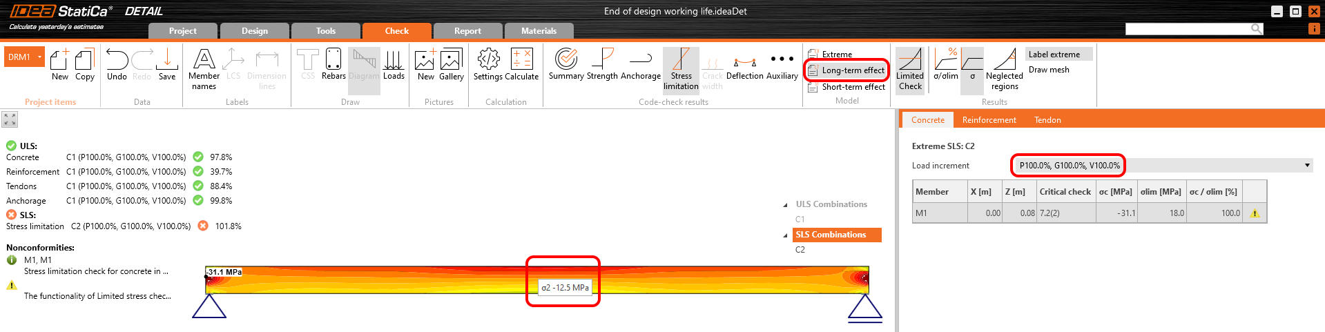
Tensione nel calcestruzzo in SLE:
La verifica della sezione SLE da Beam:
Conclusione
Infine, ecco un semplice flusso di lavoro in cui è possibile trovare la procedura sopra descritta per la progettazione di strutture in calcestruzzo precompresso in IDEA StatiCa Detail utilizzando tendini in post-tensione.
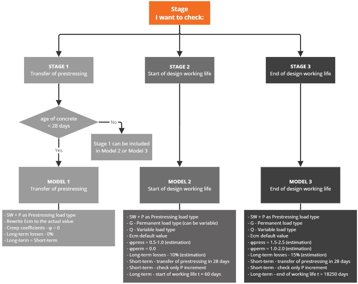
Vale la pena ribadire che per i tendini in post-tensione è necessario inserire la tensione di ancoraggio o la tensione dopo le perdite a breve termine (tipo definito dall'utente). Deve essere inserita una stima delle perdite a lungo termine dovute a viscosità, ritiro e rilassazione.
Si noti che nei modelli dell'applicazione Detail allegati per le verifiche della Fase 2 e della Fase 3 per gli incrementi V a breve termine i risultati non sono soddisfacenti. Ne consegue che per il Modello 2 e il Modello 3 per gli effetti a breve termine, è necessario considerare solo il primo incremento P (poiché nessun altro carico permanente né carico variabile verrà applicato durante l'applicazione della precompressione). Ciò è valido solo se l'età del calcestruzzo al momento dell'applicazione della precompressione è superiore a 28 giorni; in caso contrario, è necessario creare un modello speciale per la Fase 1 (per gli effetti a breve termine).
Le perdite a lungo termine per lo SLU devono essere impostate come fattore di combinazione. La stima delle perdite a lungo termine che può essere impostata nell'armatura viene presa in considerazione solo per le verifiche SLE. L'input per la stima del 15% dovrebbe essere il seguente:
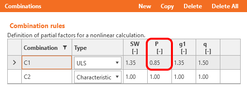
I coefficienti rinf e rsup definiti in EN 1992-1-1; 5.10.9 (1) per gli effetti della precompressione per lo SLE devono essere anch'essi presi in considerazione nelle combinazioni. Ciò significa che è necessario creare almeno due combinazioni. Si veda la figura.
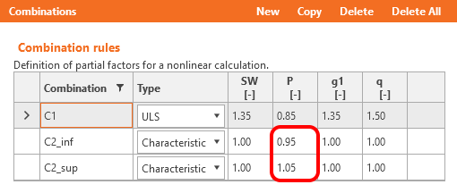
Leggere informazioni sull'implementazione di questi coefficienti nell'applicazione Beam in Come i coefficienti rinf e rsup vengono presi in considerazione per le verifiche SLE
Avete letto come utilizzare IDEA StatiCa Detail, un software di progettazione in calcestruzzo con cui è possibile, tra le altre cose, progettare travi in calcestruzzo precompresso con discontinuità. Ma non dimentichiamo IDEA StatiCa Beam, utilizzato per la progettazione di travi in calcestruzzo inclusa l'analisi dipendente dal tempo (TDA), e che abbiamo utilizzato per il confronto dei risultati.
Download allegati
- Superimposed dead load stage.ideaDet (IDEADET, 15 kB)
- End of design working life.ideaDet (IDEADET, 15 kB)
- Beam model.ideaBeam (IDEABEAM, 848 kB)
- Transfer of prestressing stage.ideaDet (IDEADET, 15 kB)