The different verifications required by EN 1992-1-1 are assessed based on the direct results provided by the model. ULS verifications are carried out for concrete strength, reinforcement strength, and anchorage (bond shear stresses).
Strength - Concrete
The concrete strength in compression is evaluated as the ratio between the maximum Equivalent principal stress σc,eq obtained from FE analysis and the limit value σc,lim = fcd.
Equivalent Principal Stress expresses the equivalent uni-axial stress for a general tri-axial stress state.
\[\sigma_{c,eq} = \sigma_{c3} - \sigma_{c1}\]
The σc,eq value can, therefore, be directly compared with uniaxial strength limits according to 1992-1-1 Cl. 3.1.7 (1).
This expression is derived from the implementation of the Mohr-Coulomb plasticity theory, conservatively assuming the angle of internal friction φ = 0°.
Strength - Reinforcement
The strength of the reinforcement is evaluated in both tension and compression as the ratio between the stress in the reinforcement at the cracks σsr and the specified limit value σs,lim:
\(σ_{s,lim} = \dfrac{k \cdot f_{yk}}{γ_s}\qquad\qquad\textsf{\small{for bilinear diagram with inclined top branch}}\)
\(σ_{s,lim} = \dfrac{f_{yk}}{γ_s}\qquad\qquad\,\,\,\,\textsf{\small{for bilinear diagram with horizontal top branch}}\)
where:
fyk is the yield strength of the reinforcement according to EN 1992-1-1 Cl. 3.2.3,
k is the ratio of tensile strength ftk to the yield stress,
\(k = \dfrac{f_{tk}}{f_{yk}}\)
γs is the partial safety factor for reinforcement.
Strength - Anchors
Anchors are checked for normal stresses in a similar way to reinforcement, where the limit value σs,lim is determined.
In addition, the NEd and VEd values are specified for anchors, which are checked against NRd,s and VRd,s according to the selected code. The code is chosen depending on the type of anchor used in Project settings.

\[ \textsf{\textit{\footnotesize{Fig. 33\qquad EN 1992-1-1 Figure 8.2 - Anchor check - Design code selection}}}\]
Since different approaches are chosen for checking anchors in different standards, the user can choose the following standards for individual anchor types:
- Anchors made of bolt material in tension and/or shear - EN 1992-4, EN 1993-1-8
- Headed studs in tension and/or shear - EN 1992-4, EN 1994-1-1
- Anchors made in tension and/or shear - EN 1992-4, EN 1992-1-1
- Anchors in compression and/or bending - EN 1993-1-1
Tension check according to EN 1992-4 - 7.2.1.3
\[N_{Rd,s} = \frac{c \cdot A_s \cdot f_{uk}}{\gamma_{Ms}}\]
where:
- c – reduction for cut threads
- fuk – minimum tensile strength of the bolt
- As – anchor bolt tensile stress area (reduced by the thread in the case of bolt material)
- \(\gamma_{Ms} = 1.2 \cdot \dfrac{f_{uk}}{f_{yk}} \ge 1.4\) – partial safety factor for stee
- fyk – minimum yield strength of the bolt
Tension check according to EN 1993-1-8 - 3.6.1
\[N_{Rd,s} = F_{t.Rd} = \frac{c \cdot k_2 \cdot f_{ub} \cdot A_s}{\gamma_{M2}}\]
where:
- c – decrease in tensile resistance of bolts with cut thread according to EN 1993-1-8 – Cl. 3.6.1. (3)
- k2 = 0.9 – factor for non-countersunk anchors
- fub – anchor bolt ultimate tensile strength
- As – anchor bolt tensile stress area (reduced by the thread in the case of bolt material)
- γM2 =1.25 – partial safety factor for bolts (EN 1993-1-8, Table 2.1)
Tension check according to EN 1992-1-1 - 3.2.7
\[N_{Rd,s} = \frac{kf_{yk}}{\gamma_{S}}\]
where:
- \(k=(f_{t}/f_{y})\) is given in Annex C
- fyk - characteristic yield strength
- γM2 =1.15 – partial safety factor for reinforcement
Compression check according to EN 1993-1-1 - 6.3
Used for all anchors subjected to a normal compression force, regardless of their material or stand-off type.
\[F_{c,Rd}=\frac{\chi\,A_s f_y}{\gamma_{M2}}\]
Where:
- \(\chi=\dfrac{1}{\Phi+\sqrt{\Phi^2-\bar{\lambda}^2}}\le 1\) – buckling reduction factor
- \(\Phi=0.5\left[1+\alpha\left(\bar{\lambda}-0.2\right)+\bar{\lambda}^2\right]\) – value to determine buckling reduction factor χ
- \(\alpha=0.49\) – imperfection factor for buckling curve c (belonging to the full circle)
- \(\bar{\lambda}=\sqrt{\dfrac{A_s f_y}{N_{cr}}}\) – relative slenderness
- As – the anchor area reduced by threads
- \(N_{cr}=\dfrac{\pi^2 E I}{L_{cr}^2}\) – Euler's critical force
- \(I=\dfrac{\pi d_s^4}{64}\) – moment of inertia of the bolt
- ds – anchor diameter reduced by threads
- \(L_{cr}=2\,l\) – buckling length; it is assumed on the safe side that the bolt is fixed in the concrete and able to rotate at the base plate freely
- \(l=l_{a}\) – length of the bolt element equal to half the base plate thickness + gap + half the bolt diameter; it is assumed on the safe side that the washer and a nut are not clamped to the concrete surface (ETAG 001 – Annex C – Cl. 4.2.2.4), see Figure 34.
Shear check according to EN 1992-4 - 7.2.2.3
For stand-off = direct, the shear without lever arm is assumed (EN 1992-4 – Cl. 7.2.2.3.1):
\[V_{Rd,s} = \frac{k_6 \cdot A_s \cdot f_{uk}}{\gamma_{Ms}}\]
For stand-off = mortar joint, the shear with lever arm is assumed (EN 1992-4 – Cl. 7.2.2.3.2):
\[V_{Rd,s} = \frac{\alpha_M \cdot M_{Rk,s}}{\gamma_{Ms} \cdot l_a}\]
where:
- k6 = 0.6 for anchors with fuk ≤ 500 MPa; k6 = 0.5 otherwise
- As – shear area of anchor reduced by threads
- fuk – anchor bolt ultimate strength
- αM = 2 – full restraint is assumed (EN 1992-4 – Cl. 6.2.2.3)
- \(M_{Rk,s} = M^{0}_{Rk,s} \left(1 - \dfrac{N_{Ed}}{N_{Rd,s}} \right)\) – characteristic bending resistance of the anchor decreased by the tensile force in the anchor
- \(M^{0}_{Rk,s} = 1.2 \cdot W_{el} \cdot f_{ub}\) – characteristic bending resistance of the anchor (ETAG 001, Annex C – Equation (5.5b))
- \(W_{el} = \dfrac{\pi d^{3}}{32}\) – section modulus of the anchor
- d – anchor bolt diameter; if the shear plane in a thread is selected (which always is for threaded rod), the diameter reduced by threads is used; otherwise, nominal diameter, dnom, is used
- NEd – tensile force in the anchor
- NRd,s – tensile resistance of the anchor
- \(l_{a} = 0.5\, d_{\mathrm{nom}} + t_{\mathrm{mortar}} + 0.5\, t_{\mathrm{bp}}\) – lever arm
- tmortar – thickness of mortar (grout)
- tbp – thickness of the base plate
- \(\gamma_{Ms} = 1.0 \cdot \dfrac{f_{uk}}{f_{yk}} \ge 1.25\) for \(f_{uk} \le 800 \text{ MPa}\) and \(\dfrac{f_{yk}}{f_{uk}} \le 0.8\); γMs = 1.5 otherwise – partial safety factor for steel failure (EN 1992-4 – Table 4.1)
Shear check according to EN 1993-1-8 - 6.2.2
Anchor shear steel resistance is determined according to EN 1993-1-8 – 6.2.2 (7) regardless of direct or mortar joint stand-off. The grout strength and thickness should be according to Cl. 6.2.5 (7).
\[V_{Rd,s} = F_{v,b,Rd} = \min \left\{ F_{1v,b,Rd} ,\, F_{2v,b,Rd} \right\}\]
where:
\[F_{1v,b,Rd} = \frac{\alpha_v \cdot f_{ub} \cdot A}{\gamma_{M2}}\]
- αv = 0.6 for grades 4.6, 5.6, 8.8, and 0.5 for grades 4.8, 5.8, 6.8, 10.9
- fub – ultimate tensile strength of the bolt material
- A – tensile stress area of the bolt, A = As, where As is the tensile stress area of the bolt (reduced by the thread)
- γM2 – safety factor - EN 1993-1-8 – Table 2.1
\[F_{2v,b,Rd} = \frac{\alpha_b \cdot f_{ub} \cdot A_s}{\gamma_{M2}}\]
- \(\alpha_b = 0.44 - 0.0003\, f_{yb}\)
- αb is a coefficient depending on the yield strength of the anchor bolt
- fyb – anchor yield strength; 235 MPa ≤ fyb ≤ 640 MPa
- fub – anchor tensile strength
- As – tensile stress area (reduced by the thread)
Shear check according to EN 1993-1-1 - 6.2.6
These code checks are applied to anchors that are connected to the base plate with a gap or a directly loaded anchor with a projected length more than 0.5 times their diameter.
\[V_{pl,Rd}=\frac{A_v f_y/\sqrt{3}}{\gamma_{M2}}\]
where:
- AV = 0.844 As – shear area
- As – bolt area reduced by threads
- fy – bolt yield strength
- γM2 – partial safety factor (defined in the Project settings)
Shear check according to EN 1994-1-1 - 6.6.3.1
\[V_{Rd,s} = P_{Rd} = \frac{0.8 \, f_u \, \pi \, d^2}{4 \, \gamma_v}\]
where:
- γv is the partial factor for shear connection per EN 1994-1-1 chap. 2.4.1.2. The recommended value for γv is 1.25
- d is the diameter of the shank of the stud, 16 mm ≤ d ≤ 25 mm;
- fu is the specified ultimate tensile strength of the material of the stud, but not greater than 500 MPa.
In EN 1994-1-1, clause 6.6.3.1 also provides Equation (6.19), which limits the shear resistance of a stud by the punching (bearing) capacity of the concrete. In IDEA StatiCa Detail, this failure mode is not checked by a separate code formula in the post-processing. Instead, it is built directly into the nonlinear finite element analysis as a stop criterion: the analysis is terminated before the shear force in an anchor reaches the corresponding PRd
from Equation (6.19). This approach is used because Equation (6.19) is valid only for headed studs welded to the steel plate and for stud diameters in the range 16 mm ≤ d ≤ 25 mm, as specified in 6.6.3.1.
To cover a wider range of practical cases, we created a series of 3D reference models in Abaqus with anchor diameters from 8 mm to 50 mm and concrete strengths from C16/20 to C50/60. The studs were modeled either welded rigidly to the base plate or connected by a pinned (hinged) joint. The material models and contact parameters in Detail were then calibrated against these Abaqus simulations, which were themselves verified against Equation (6.19) within its validity range. This stop criterion is valid for all anchor types and all EN codes.
Bending check according to EN 1993-1-1 - 6.2.5
\[M_{pl,Rd}=\frac{W_{pl} f_y}{\gamma_{M2}}\]
Where:
- \(W_{pl}=\dfrac{d_s^{3}}{6}\) – section modulus of the bolt
- ds – anchor diameter reduced by threads
- fy – material yield strength
- γM2 – partial safety factor (defined in the Project settings)
Acting design bending moment MEd - If the shear load acts with a lever arm, a bending moment acting on the fastener shall be accounted for. The design bending moment acting on the fastener is calculated according to EN 1993-1-1 Formula (6.1):
\[M_{Ed}=V_{Ed}\cdot\frac{l_a}{\alpha_M}\]
where:
- VEd - is the shear load acting on the fastener under consideration
- la = a3 + e1
- a3 = 0.5dnom, where dnom is the anchor diameter
- e1 - is the distance between the shear load and the concrete surface, neglecting the thickness of any levelling grout
- αM = 2 – full restraint is assumed (EN 1992-4 – Cl. 6.2.2.3)

\[ \textsf{\textit{\footnotesize{Fig. 34\qquad Buckling length}}}\]
Interaction of tension and shear in anchor steel
The interaction of tension and shear per EN 1993-1-8 is implicitly included in the anchor shear check.
The interaction of tension and shear per EN 1992-4 is determined separately for steel and concrete failure modes according to Table 7.3. The interaction in steel is checked for each anchor separately.
\[\left( \frac{N_{Ed}}{N_{Rd,s}} \right)^{2}+\left( \frac{V_{Ed}}{V_{Rd,s}} \right)^{2}\le 1\]
EN 1994-1-1 states in Article 6.6.3.2 that if the anchor tensile force is greater than 0.1PRd, the check is not covered by this standard. In such a case, the interaction is assessed in accordance with EN 1992-4 in the application. In such a case, the shear check should not be considered according to EN 1994-1-1.
Interaction of tension or compression and bending in anchor steel EN 1993-1-1 - 6.2.1
\[\frac{N_{Ed}}{N_{Rd}}+\frac{M_{Ed}}{M_{Rd}}\le 1\]
where:
- NEd – tensile (positive) or compressive (negative sign) design force
- NRd – tensile (positive, Ft,Rd) or compressive (negative sign, Fc,Rd) design resistance
- MEd – design bending moment
- MRd = Mpl,Rd – design bending resistance
Pull-out check for headed anchors (Washer plates and Headed studs)
For headed anchors, an additional stop criterion is implemented to check the concrete bearing (crushing) above the anchor head - pull-out. During the analysis, the compressive force transferred through the head-to-concrete contact is monitored and compared with the limit value given by EN 1992-4, Clause 7.2.1.5 (pull-out failure of headed fastenings).
\[N_{Rd,p} = k_2 \cdot A_h \cdot f_{ck} / \gamma_{Mp}\]
where:
- Ah is the load bearing area of the head of the fastener (without the shank area).
- fck is the characteristic compressive strength of concrete - EN 1992-1-1 Cl. 3.1.2
- γMp is taken in the application as γMp = γc with the default value of 1.5
- k2 is always taken as 7.5, i.e. the value for cracked concrete. This is consistent with the CSFM approach used in Detail, where the tensile strength of concrete is neglected and the concrete is assumed to be cracked in tension.
Once the contact force reaches this code-based limit, the stop criterion is triggered and the analysis is terminated before the design pull-out resistance is exceeded.
Anchorage - Bond stress
The bond shear stress is evaluated independently as the ratio between the bond stress τb calculated by FE analysis and the ultimate bond strength fbd, according to EN 1992-1-1 chap. 8.4.2:
\[\frac{τ_{b}}{f_{bd}}\le 1\]
\[f_{bd} = 2.25 \cdot η_1\cdot η_2\cdot f_{ctd}\]
where:
- fctd is the design value of concrete tensile strength according to EN 1992-1-1 Cl. 3.1.6 (2). Due to the increasing brittleness of higher-strength concrete, fctk,0.05 is limited to the value for C60/75 according to EN 1992-1-1 Cl. 8.4.2 (2)
- η1 is a coefficient related to the quality of the bond condition and the position of the bar during concreting (Fig. 34).
- η1 = 1.0 when ‘good’ conditions are obtained and
- η1 = 0.7 for all other cases and for bars in structural elements built with slip-forms, unless it can be shown that ‘good’ bond conditions exist
- η2 is related to the bar diameter:
η2 = 1.0 for Ø ≤ 32 mm
η2 = (132 - Ø)/100 for Ø > 32 mm
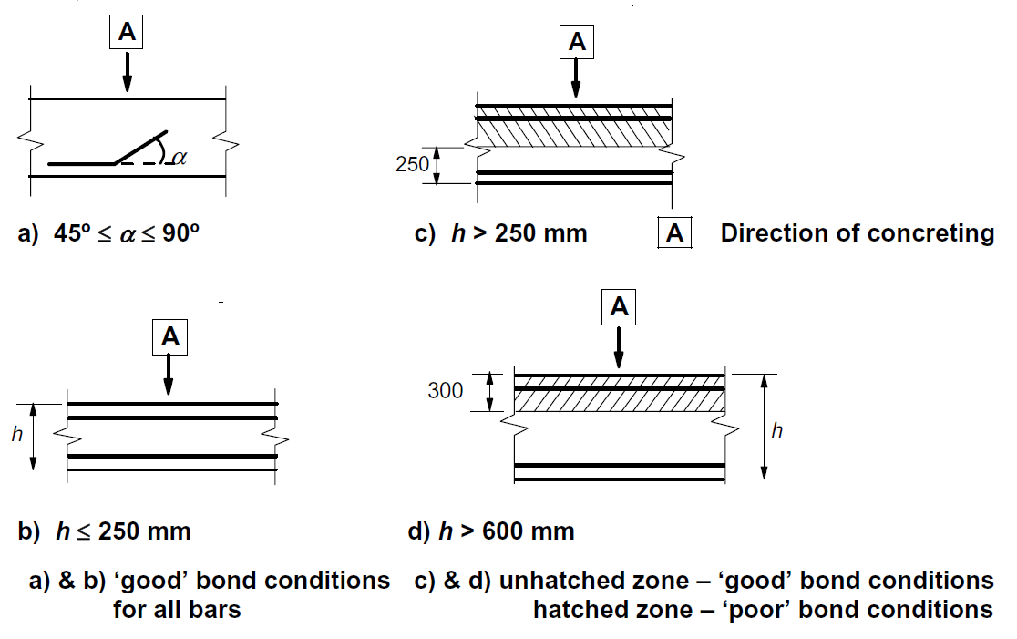
\[ \textsf{\textit{\footnotesize{Fig. 35\qquad EN 1992-1-1 Figure 8.2 - Description of bond conditions.}}}\]
In IDEA StatiCa Detail, the bond conditions are taken into account according to Fig. 34 c) and d). The direction of concreting can be set in the application for each project item as follows:
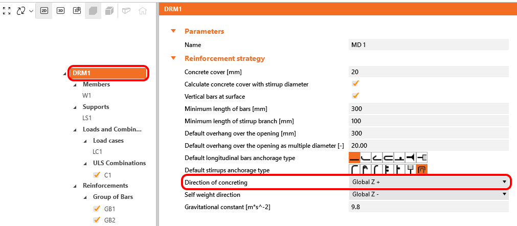
\[ \textsf{\textit{\footnotesize{Fig. 36\qquad Direction of concreting}}}\]
These verifications are carried out with respect to the appropriate limit values for the respective parts of the structure (i.e., in spite of having a single grade both for concrete and reinforcement material, the final stress-strain diagrams will differ in each part of the structure due to tension stiffening and compression softening effects).
Anchorage - Total force
Total force Ftot and Limit force Flim
The total force Ftot is a result of the finite element analysis and can be defined in two ways.
\[F_{tot}=A_{s}\cdot \sigma_{s}\]
where As is the area of the reinforcement bar and σs is the stress in the bar.
Or as a sum of the anchorage force Fa and the bond force Fbond.
\[F_{tot}=F_{a}+F_{bond}\]
where Fa is the actual force in the anchorage spring and Fbond is the bond force that can be obtained by integrating the bond stress τb along the length of reinforcement bar l.
\[F_{bond}=C_{s} \cdot \int_{0}^{l}\tau_{b}\left( x \right)dx\]
Cs is the circumference of the reinforcement bar.
The limit force Flim is the maximum force in the element of the rebar considering the ultimate strength of the rebar and also anchoring conditions (bond between concrete and reinforcement and anchorage hooks, loops, etc.).
\[F_{lim}=min\left( F_{lim,bond}+F_{au},F_{u} \right)\]
\[F_{u}=k\cdot f_{yd}\cdot A_{s}\]
\[F_{au}=\beta\cdot k\cdot f_{yd}\cdot A_{s}\]
\[F_{lim,bond}=C_{s}\cdot l \cdot f_{bd}\]
where Cs is the circumference of the reinforcement bar, and l is the length from the beginning of the rebar to the point of interest.
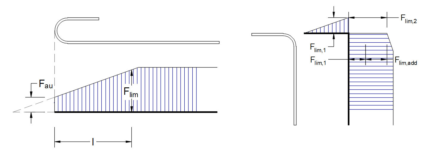
\[ \textsf{\textit{\footnotesize{Fig. 37\qquad Definition of the limit force Flim}}}\]
\[F_{lim,2}=F_{lim,1}+F_{lim,add}\]
where Flim,add is the additional force calculated from the magnitude of the angle between neighboring elements. Flim,2 must always be lower than Fu.
Anchorage types at the end of Reinforcement (Anchors and Rebars)
The available anchorage types in 3D CSFM include a straight bar (i.e., no anchor end reduction), bend, hook, loop, welded transverse bar, perfect bond, and continuous bar. All these types, along with the respective anchorage coefficients β, are shown in Fig. 36 for longitudinal reinforcement and in Fig. 37 for stirrups. The values of the adopted anchorage coefficients are in accordance with EN 1992-1-1 section 8.4.4 Tab. 8.2. It should be noted that in spite of the different available options, 3D CSFM distinguishes three types of anchorage ends: (i) no reduction in the anchorage length, (ii) a reduction of 30% of the anchorage length in the case of a normalized anchorage, and (iii) perfect bond.

\[ \textsf{\textit{\footnotesize{Fig. 38\qquad Available anchorage types and respective anchorage coefficients for longitudinal reinforcing bars in the 3D CSFM:}}}\]
\[ \textsf{\textit{\footnotesize{(a) straight bar; (b) bend; (c) hook; (d) loop; (e) welded transverse bar; (f) perfect bond; (g) continuous bar.}}}\]
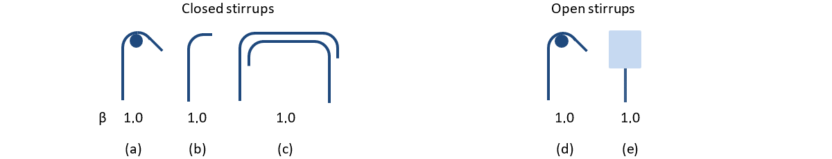
\[ \textsf{\textit{\footnotesize{Fig. 39\qquad Available anchorage types and respective anchorage coefficients for stirrups.}}}\]
\[ \textsf{\textit{\footnotesize{Closed stirrups: (a) hook; (b) bend; (c) overlap. Open stirrups: (d) hook; (e) continuous bar.}}}\]
In order to comply with EN 1992-1-1, the anchorage spring should be used in the calculation, the anchorage spring is modified by the β coefficient, so the user must use one of the available anchorage types when defining the reinforcement start and end conditions.