
Catálogo de estados límite y requisitos de cálculo según AISC
Introducción
El diseño de uniones de acero estructural requiere la evaluación de numerosos estados límite, la consideración de múltiples efectos de comportamiento y el cumplimiento de numerosos requisitos. La Especificación AISC, el Manual AISC y otras referencias describen los métodos de diseño utilizados en la práctica estadounidense. Actualmente, los métodos más ampliamente utilizados se basan principalmente en cálculos que pueden realizarse a mano. Sin embargo, los avances en hardware y software informático permiten un tipo diferente de diseño basado en el análisis estructural no lineal.
El uso del análisis no lineal en el diseño puede ser ventajoso para uniones complejas o singulares, donde las hipótesis de los cálculos tradicionales no están demostradas. No obstante, se aplican los mismos estados límite, consideraciones de diseño y requisitos de cálculo. Un buen diseño de uniones proviene de ingenieros que conocen estos criterios de diseño y cómo sus herramientas los contemplan.
Este documento pretende ser una relación detallada, aunque no exhaustiva, de los estados límite, consideraciones de diseño y requisitos de cálculo relevantes para el diseño de acero estructural, así como una descripción de cómo se consideran en los cálculos tradicionales y en IDEA StatiCa mediante el método de los elementos finitos basado en componentes.
Este documento se actualiza continuamente, ya que los ejercicios de verificación e investigación siguen en curso.
El contenido de este artículo hace referencia a la Especificación AISC 2022 y a la 16ª Edición del Manual AISC.
Estados límite
Rotura de soldadura
La Especificación AISC incluye disposiciones para soldaduras en ranura, soldaduras en ángulo y soldaduras de tapón y ranura. De estas, las soldaduras en ranura de penetración completa (CJP) y las soldaduras en ángulo son los únicos tipos que actualmente pueden definirse en IDEA StatiCa.
Las soldaduras en ranura CJP y las soldaduras a tope en IDEA StatiCa se modelan conectando directamente los componentes mediante restricciones multipunto. Las restricciones multipunto no introducen flexibilidad. Además, la resistencia de estas soldaduras no se verifica, ya que la resistencia de las soldaduras en ranura CJP está controlada por el metal base.
Las soldaduras en ángulo también se modelan mediante restricciones multipunto y un elemento de lámina de soldadura equivalente que aproxima el comportamiento elastoplástico de la soldadura. Las fuerzas en estos elementos de lámina se extraen y se utilizan como resistencias requeridas para su comparación con las resistencias disponibles calculadas según la Especificación AISC.
La resistencia disponible de las soldaduras se define en la Sección J2.4 de la Especificación AISC. Para las soldaduras en ángulo, la resistencia nominal es el producto de la tensión nominal del metal de aportación, Fnw, el área efectiva de la soldadura, Awe, y un factor de incremento de resistencia direccional, kds. La Tabla J2.5 de la Especificación AISC establece Fnw = 0,6FEXX y hace referencia a la Sección J2.2a de la Especificación AISC para la definición de Awe. Para cada segmento de soldadura, Awe se toma como el espesor de garganta multiplicado por la longitud del segmento de soldadura. Las reducciones a la longitud efectiva para soldaduras largas de la Sección J2.2b de la Especificación AISC no se aplican; sin embargo, los efectos de las soldaduras largas se capturan explícitamente tal como se describe en la entrada sobre Compatibilidad de Deformaciones en Uniones Largas.
El factor de incremento de resistencia direccional se define en la Sección J2.4 de la Especificación AISC. Cuando se considera la compatibilidad de deformaciones de los distintos elementos de soldadura (como ocurre en IDEA StatiCa, ya que la rigidez de las soldaduras y los elementos de conexión se modelan explícitamente), kds es función del ángulo entre la línea de acción de la fuerza requerida y el eje longitudinal de la soldadura. IDEA StatiCa determina la línea de acción a partir de las fuerzas internas en el elemento de lámina de soldadura equivalente y calcula kds y la resistencia nominal para cada segmento de soldadura.
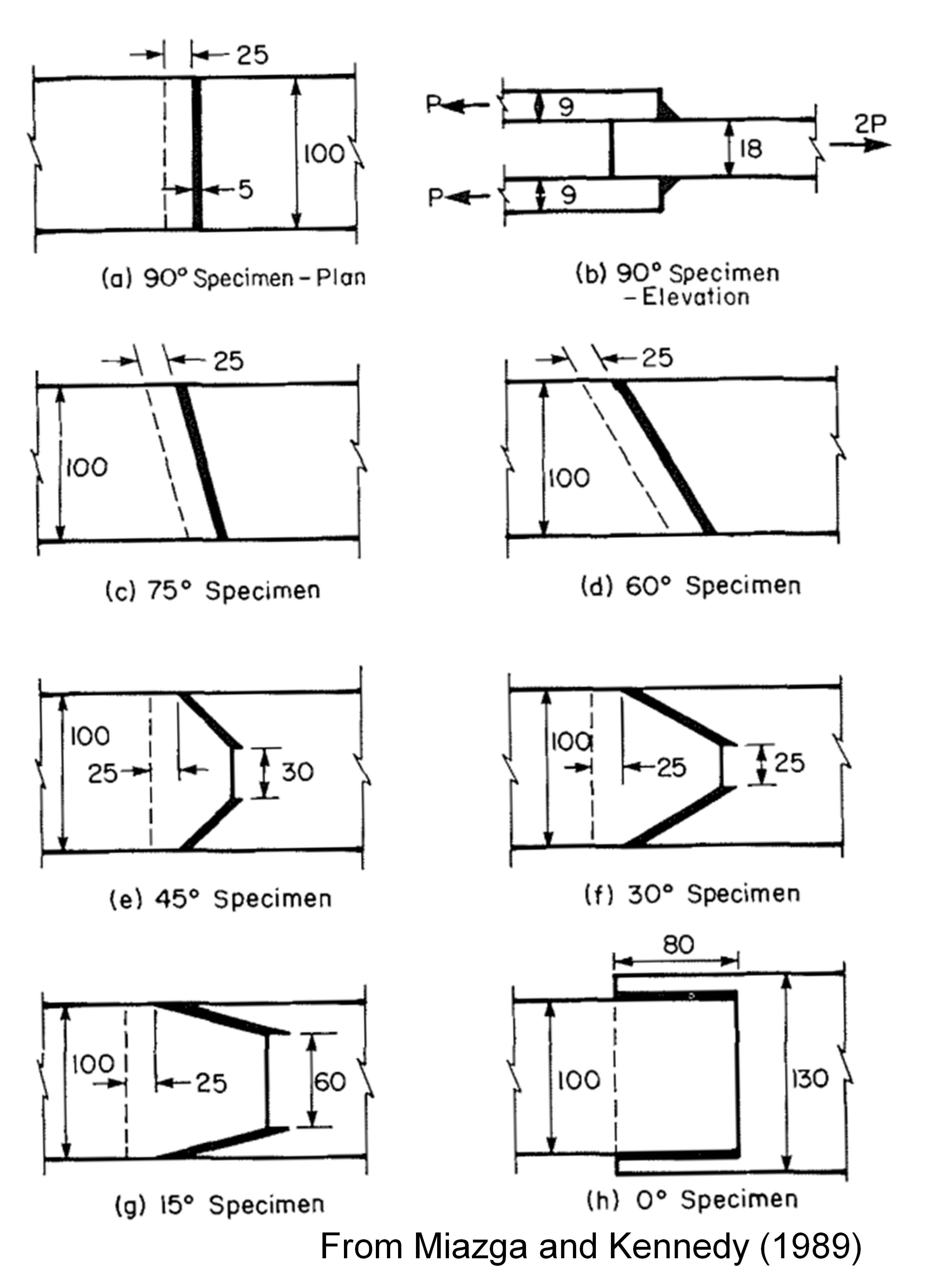
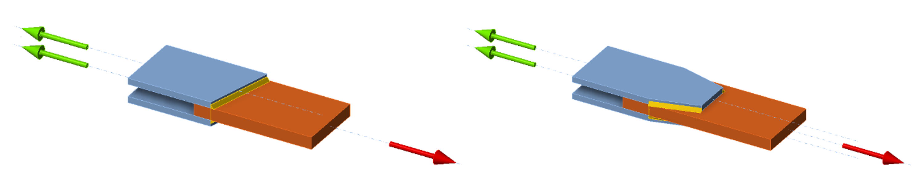
Para ilustrar el efecto del incremento de resistencia direccional, considérense los especímenes soldados ensayados experimentalmente por Miazga y Kennedy (1989). Los especímenes tenían ángulos de carga de 0, 15, 30, 45, 60, 75 y 90 grados, tal como se muestra en la figura siguiente, donde las unidades son milímetros. Las placas se fabricaron con acero CAN3-G40.21-M8 grado 300W. Las placas exteriores tenían una resistencia a la fluencia medida de 52,8 ksi. Las placas interiores tenían una resistencia a la fluencia medida de 50,2 ksi. Se utilizaron electrodos E48014 con una resistencia nominal de FEXX = 70 ksi.
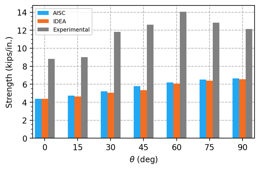
Las cargas aplicadas máximas permitidas se determinaron para cada espécimen en IDEA StatiCa utilizando modelos con propiedades medidas del material de las placas, propiedades nominales del metal de aportación e incluyendo los factores de resistencia. Las cargas aplicadas máximas permitidas se normalizaron por la longitud total de soldadura en la unión y se muestran en la figura siguiente. También se muestran la resistencia de cálculo según la Especificación AISC (incluyendo el factor de incremento de resistencia direccional y el factor de resistencia) y la resistencia experimental.
El ángulo de carga medido desde el eje longitudinal de la soldadura para cada espécimen, tal como lo proporciona IDEA StatiCa en los resultados de soldadura, se indica en la tabla siguiente.
| Geométrico \(\theta\) (deg) | IDEA \(\theta\) (deg) |
| 0 | 14,7 |
| 15 | 21,1 |
| 30 | 34,0 |
| 45 | 49,1 |
| 60 | 58,8 |
| 75 | 72,6 |
| 90 | 89,9 |
Las resistencias obtenidas con IDEA StatiCa y según la Especificación AISC son ambas muy inferiores a las resistencias experimentales. Existen varias razones por las que las resistencias experimentales son mayores: no incluyen factores de resistencia, la resistencia real del metal de aportación es probablemente superior a la resistencia nominal, y el área de fallo real de la soldadura es probablemente mayor que la asumida en los cálculos de diseño.
Las resistencias obtenidas con IDEA StatiCa son ligeramente inferiores a las de la Especificación AISC, pero ambas muestran un incremento con el ángulo de carga. Además, el ángulo geométrico del espécimen difiere del ángulo de carga medido desde el eje longitudinal de la soldadura que proporciona IDEA StatiCa. Estas diferencias se producen porque las soldaduras se dividen en segmentos cortos al modelarse en IDEA StatiCa. A diferencia de los cálculos tradicionales, donde se asume que las solicitaciones a lo largo de la longitud de la soldadura son uniformes, los segmentos de soldadura experimentan diferentes solicitaciones en función de la rigidez de la soldadura y de los elementos de conexión. El ángulo que proporciona IDEA StatiCa corresponde al segmento de soldadura con mayor ratio de utilización. Con frecuencia, este es un segmento en el extremo de una soldadura. En estos especímenes, el efecto agregado de las solicitaciones no uniformes supone una ligera reducción de la resistencia.
Se aplica un caso especial para las soldaduras en ángulo en los extremos de perfiles HSS rectangulares cargados a tracción, donde kds = 1,0. En IDEA StatiCa, el factor de incremento de resistencia direccional no se utiliza para soldaduras en ángulo en los extremos de perfiles HSS rectangulares, independientemente de la carga.
La Sección J2.4 de la Especificación AISC también define la resistencia del metal base. Para las soldaduras en ángulo, la Tabla J2.5 de la Especificación AISC hace referencia a la Sección J4 de la Especificación AISC para las verificaciones del metal base. Las verificaciones de la resistencia del metal base se describen con mayor detalle en la entrada sobre Resistencia del Metal Base de Soldadura.
Resistencia del Metal Base de Soldadura
En las uniones soldadas, la resistencia de los elementos de conexión adyacentes a la soldadura se denomina resistencia del metal base. En muchos casos, los posibles estados límite pueden identificarse y la resistencia disponible del metal base puede calcularse utilizando las disposiciones de la Sección J4 de la Especificación AISC. La evaluación de estos estados límite en IDEA StatiCa se describe en las entradas sobre los estados límite individuales, incluyendo Plastificación a Tracción, Rotura a Tracción, Plastificación y Rotura a Cortante y Rotura por Bloque de Cortante.
Sin embargo, en algunas uniones, los posibles estados límite adyacentes a la soldadura son difíciles de identificar y la resistencia disponible del metal base no puede calcularse directamente a mano. Para estos casos, el Manual AISC proporciona las Ecuaciones 9-6 y 9-7 para el espesor mínimo del metal base que se corresponde con la soldadura bajo ciertas hipótesis. Esta ecuación no se evalúa en IDEA StatiCa, ya que los posibles estados límite del metal base no necesitan identificarse a priori y la resistencia se evalúa con el límite de deformación plástica del 5%. No obstante, los ingenieros pueden seguir utilizando este límite para dimensionar las soldaduras y los elementos de conexión.
IDEA StatiCa ofrece la opción de verificar la capacidad del metal base en la cara de fusión. Esta verificación puede activarse en la ventana "Configuración de código". Esta verificación no se realiza habitualmente en la práctica estadounidense y generalmente no es necesaria cuando el metal de aportación está adecuadamente seleccionado para el metal base. El comentario a la Sección J2.4 de la Especificación AISC indica que los ensayos han demostrado que la tensión en la zona de fusión no es determinante para establecer la resistencia a cortante de las soldaduras en ángulo.
Rotura de Pernos a Cortante y Tracción
La resistencia disponible de los pernos sometidos a tracción o cortante se define en la Sección J3.7 de la Especificación AISC. La resistencia disponible de los pernos sometidos a tracción y cortante combinados se define en la Sección J3.8 de la Especificación AISC. IDEA StatiCa utiliza estas disposiciones directamente para calcular las resistencias disponibles, comparándolas con las resistencias requeridas determinadas a partir del análisis no lineal. Según se especifica, la resistencia a tracción requerida determinada a partir del análisis no lineal incluye la tracción resultante de la fuerza de palanca.
Una nota a pie de página en la Tabla J3.2 de la Especificación AISC requiere que la tensión nominal a cortante, Fnv, de los pernos A307 se reduzca cuando el agarre del perno sea superior a cinco veces su diámetro. Esta reducción no está implementada en IDEA StatiCa. Por lo tanto, la tensión nominal a cortante de los pernos A307 largos debe ajustarse manualmente en la pestaña de materiales.
Aplastamiento y Desgarro en Orificios de Pernos
La resistencia de los pernos a cortante puede estar limitada por el aplastamiento o el desgarro en los orificios de los pernos. En ocasiones es práctica habitual evaluar el aplastamiento y el desgarro de forma independiente a la rotura a cortante del perno. Sin embargo, los grupos de pernos pueden fallar con algunos pernos rotos y otros desgarrados. Una nota de usuario en la Sección J3.7 de la Especificación AISC indica: "La resistencia efectiva de un elemento de fijación individual puede tomarse como el menor valor entre la resistencia a cortante del elemento de fijación según la Sección J3.7 o la resistencia al aplastamiento o desgarro en el orificio del perno según la Sección J3.11. La resistencia del grupo de pernos se toma como la suma de las resistencias efectivas de los elementos de fijación individuales."
IDEA StatiCa evalúa la resistencia de cada perno individualmente, con las resistencias requeridas determinadas a partir del análisis no lineal y las resistencias disponibles calculadas utilizando las disposiciones de la Especificación AISC. Esta evaluación cumple con la nota de usuario de la Sección J3.7 de la Especificación AISC. Sin embargo, IDEA StatiCa no simplemente suma las resistencias efectivas de los elementos de fijación individuales. El enfoque adoptado por IDEA StatiCa puede dar lugar a una subestimación conservadora de la resistencia.
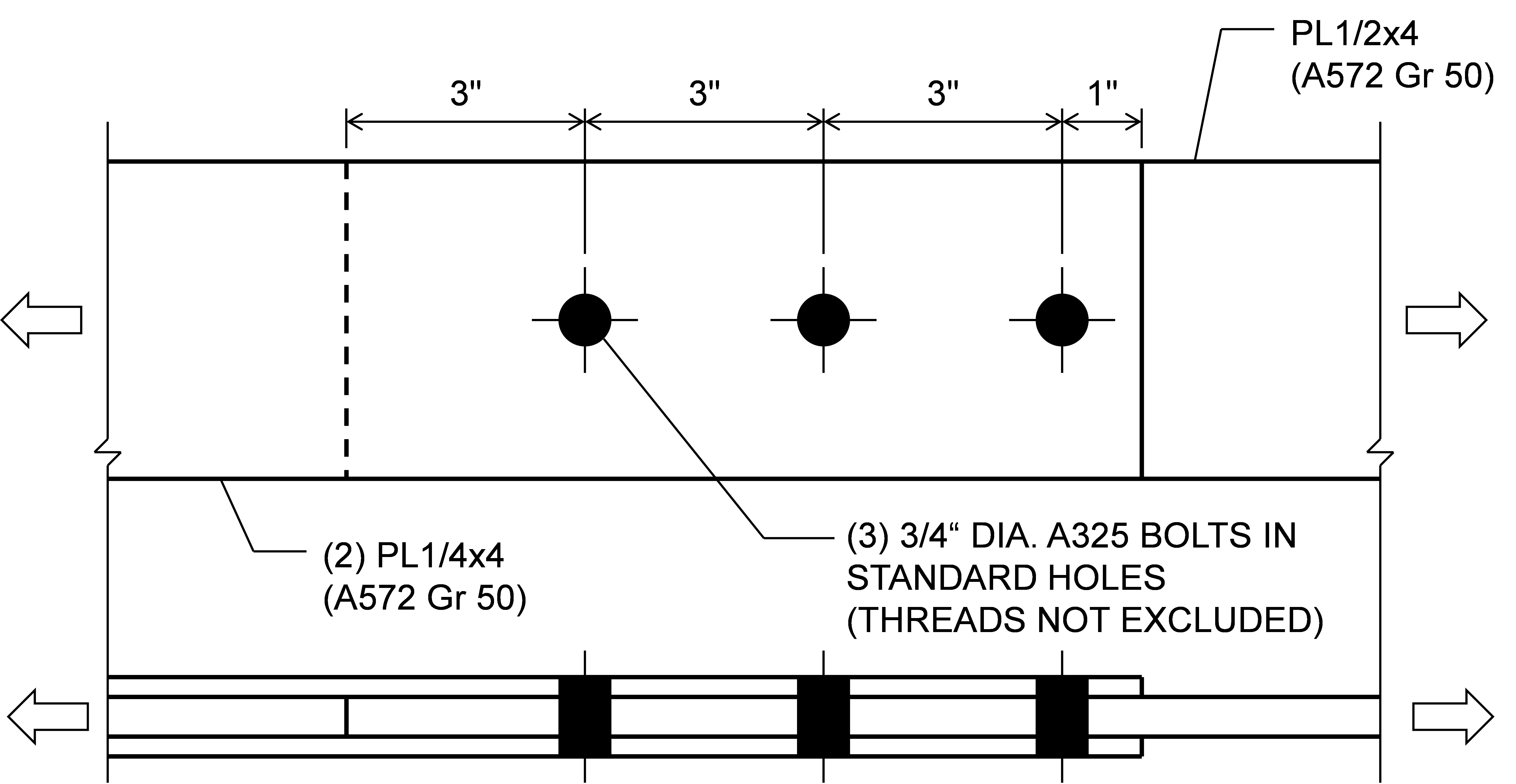
Considérese la unión de tres pernos mostrada a continuación. La unión es corta y la rigidez de los tres pernos es igual porque la respuesta carga-deformación de los pernos en IDEA StatiCa no depende de la distancia al borde, por lo que la carga aplicada se reparte aproximadamente por igual entre los pernos. La resistencia del perno con una distancia al borde de 1 pulg. está controlada por el desgarro. IDEA StatiCa indica fallo cuando el primer perno alcanza el 100% de utilización. Dado que el perno con una distancia al borde de 1 pulg. tiene la menor resistencia disponible (ϕrn = ϕ1,2dtFu = 17,4 kips), alcanza el 100% de utilización primero. Los demás pernos son más resistentes (ϕrn = 35,8 kips, Tabla 7-1 del Manual AISC) pero no alcanzan el 100% de utilización, resultando en una resistencia de la unión de 52,5 kips. Mediante cálculos tradicionales, se asume que cada perno alcanza su resistencia efectiva, resultando en una resistencia de la unión de 89,0 kips, un 70% mayor que la resistencia obtenida con IDEA StatiCa.
Unión atornillada de tres pernos
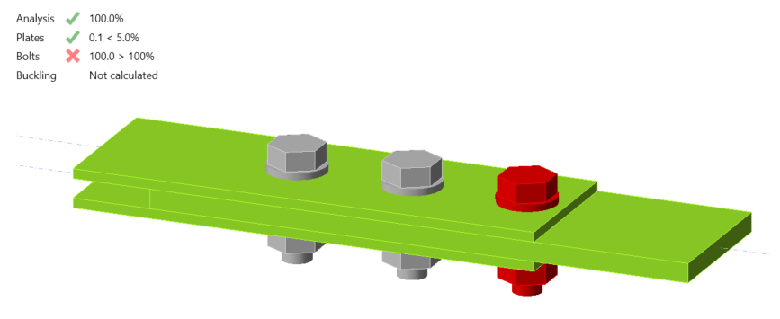
Unión atornillada de tres pernos con 57,5 kips de carga aplicada
En la Sección J3.11a de la Especificación AISC se proporcionan dos conjuntos de ecuaciones: uno cuando la deformación en el orificio del perno bajo carga de servicio es una consideración de diseño, y otro cuando no lo es. La elección de si la deformación en el orificio del perno bajo carga de servicio es una consideración de diseño puede realizarse en la ventana "Configuración de código".
En la Sección J3.11a de la Especificación AISC también se proporcionan ecuaciones diferentes para orificios ranurados largos cuando la ranura es perpendicular a la dirección de la fuerza. Los orificios ranurados pueden definirse en IDEA StatiCa mediante el editor de placas. Las ecuaciones de aplastamiento y desgarro de la Especificación AISC para orificios ranurados largos se utilizan para todos los orificios ranurados en IDEA StatiCa, independientemente de la longitud de la ranura.
La Sección J3.11b de la Especificación AISC requiere el uso de las disposiciones de aplastamiento de la Sección J7 para pernos o barras que atraviesan completamente un elemento de caja no rigidizado o un perfil hueco estructural (HSS). Esta disposición no está implementada en IDEA StatiCa y el aplastamiento se evalúa en dichas uniones como si fueran uniones atornilladas ordinarias con todas las capas en contacto firme. En el informe se proporciona una advertencia si la longitud de agarre del perno es mayor que la suma de los espesores de las placas conectadas.
Al evaluar el desgarro, IDEA StatiCa determina la distancia libre, en la dirección de la fuerza, entre el borde del orificio y el borde del orificio adyacente o el borde del material, lc, utilizando la dirección de la fuerza para cada perno obtenida del análisis no lineal. Esta función es especialmente útil para grupos de pernos con carga excéntrica, donde la dirección de la fuerza varía de un perno a otro. El estado límite de desgarro fue investigado para uniones de placa de ménsula en este artículo y para uniones de placa de aleta simple en este artículo.
Aplastamiento (Plastificación Local a Compresión)
La Sección J7 de la Especificación AISC define la resistencia disponible para el estado límite de aplastamiento (plastificación local a compresión). Estas disposiciones se aplican a casos específicos de contacto entre componentes de acero, pero no están implementadas en IDEA StatiCa.
Para superficies acabadas y extremos de rigidizadores de apoyo ajustados, aunque la presión de contacto en el apoyo no se verifica frente al límite prescrito en la Especificación AISC, las tensiones en los contactos pueden representarse gráficamente y la plastificación de los componentes de acero suele proporcionar un límite más condicionante, ya que la presión de apoyo admisible supera la resistencia a la fluencia.
IDEA StatiCa evalúa la resistencia al aplastamiento de pernos o barras que atraviesan completamente un elemento de caja o HSS no rigidizado como si fueran uniones atornilladas ordinarias con todas las capas en contacto firme, sin utilizar las disposiciones de la Sección J7 de la Especificación AISC. En el informe se proporciona una advertencia si la longitud de agarre del perno es mayor que la suma de los espesores de las placas conectadas. Véase también Aplastamiento y Desgarro en Orificios de Pernos.
Los rodillos y balancines de expansión no pueden modelarse en IDEA StatiCa. Los pasadores se introdujeron en IDEA StatiCa en la versión 24.0 y actualmente solo están disponibles para el diseño según Eurocode.
Deslizamiento
Las uniones deben diseñarse como resistentes al deslizamiento cuando están sometidas a cargas de fatiga con inversión de la dirección de carga, cuando utilizan orificios sobredimensionados, cuando el deslizamiento en las superficies de contacto sería perjudicial para el comportamiento de la estructura, y por otras razones. La resistencia disponible para el estado límite de deslizamiento se define en la Sección J3.9 de la Especificación AISC, con disposiciones adicionales en la Sección J3.10 para tracción y cortante combinados en uniones resistentes al deslizamiento. IDEA StatiCa utiliza estas disposiciones directamente para calcular las resistencias disponibles, que se comparan con las resistencias requeridas determinadas a partir del análisis no lineal.
El coeficiente de deslizamiento, μ, se define en la configuración de código. El factor para rellenos, hf, se determina automáticamente.
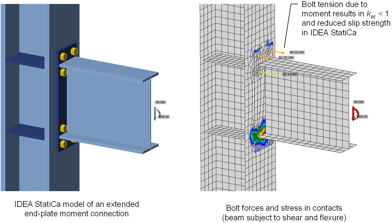
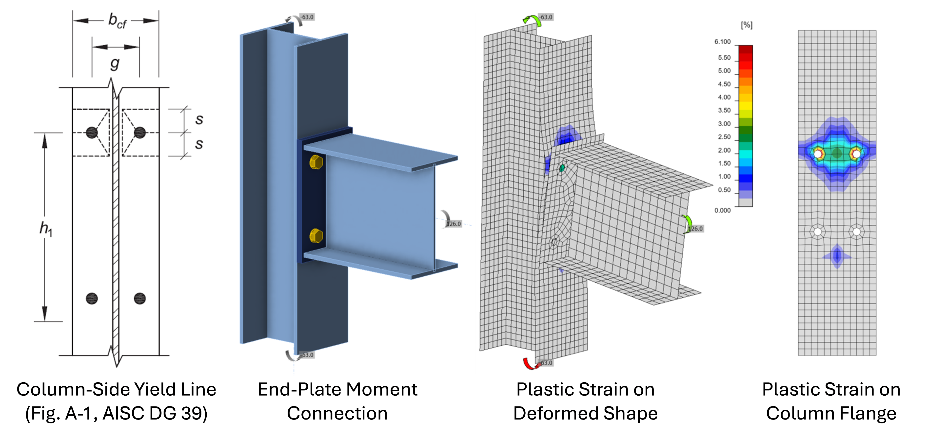
Pueden producirse diferencias entre IDEA StatiCa y los cálculos manuales debido al factor de reducción por tracción, ksc, definido en la Sección J3.10 de la Especificación AISC. IDEA StatiCa utiliza la tracción en el perno obtenida del análisis no lineal para calcular ksc, incluso si la tracción en el perno no fue causada por una tracción aplicada que reduzca la fuerza de apriete neta. Por ejemplo, en una unión de momento con placa de testa extendida con una unión resistente al deslizamiento entre la placa de testa y el ala del pilar (como se muestra a continuación), el momento en la viga provoca tracción en los pernos en IDEA StatiCa. Físicamente, cualquier pérdida de fuerza de apriete cerca de los pernos en el lado a tracción de la viga debida al momento se compensará con un aumento de la fuerza de apriete cerca de los pernos en el lado a compresión de la viga. En los cálculos manuales, el factor ksc no se utilizaría para esta unión (a menos que la viga tenga una fuerza de tracción neta). Pero dado que IDEA StatiCa evalúa los pernos individualmente, ksc se aplica de forma conservadora a los pernos en el lado a tracción de la viga, reduciendo la resistencia global al deslizamiento de la unión. La tracción incidental en una unión predominantemente cargada a cortante y la tracción debida a la fuerza de palanca también se incluyen de forma conservadora al calcular ksc en IDEA StatiCa.
La Sección J3.9 de la Especificación AISC requiere que las uniones resistentes al deslizamiento se diseñen también para los estados límite de las uniones de tipo aplastamiento, además del deslizamiento. IDEA StatiCa no verifica la rotura del perno, el aplastamiento ni el desgarro para los pernos designados para transmitir fuerzas por fricción. Además, las uniones resistentes al deslizamiento se modelan de forma diferente a las uniones de tipo aplastamiento en IDEA StatiCa. En las uniones resistentes al deslizamiento, las fuerzas se transmiten de una placa a otra sobre un área mayor, más representativa de la transmisión de fuerzas por fricción. La mayor distribución de las fuerzas de transmisión puede dar lugar a una mayor resistencia de los elementos de conexión para estados límite como la rotura por bloque de cortante. En la mayoría de las uniones, la resistencia al deslizamiento es menor que la resistencia para los estados límite de las uniones de tipo aplastamiento. Sin embargo, los ingenieros deben ser conscientes de estas limitaciones y tenerlas en cuenta en el diseño. Se recomienda analizar las uniones resistentes al deslizamiento dos veces en IDEA StatiCa: una como unión resistente al deslizamiento (es decir, con el tipo de transmisión de fuerza cortante configurado como "Fricción") y otra como unión de tipo aplastamiento (es decir, con el tipo de transmisión de fuerza cortante configurado como "Aplastamiento – interacción tracción/cortante") para garantizar que todos los estados límite se evalúan adecuadamente.
Plastificación a Tracción
La plastificación a tracción es uno de los estados límite más fundamentales en el diseño de acero estructural. La resistencia nominal a la plastificación por tracción se define en la Sección D2 de la Especificación AISC (2022) para elementos a tracción y en la Sección J4.1 para elementos de conexión, como el producto del límite elástico mínimo especificado, Fy, por el área bruta, Ag. A pesar de la simplicidad de esta ecuación, no se utiliza para evaluar la resistencia en IDEA StatiCa. Los elementos y los elementos de conexión se modelan en IDEA StatiCa con elementos de lámina a los que se asigna una relación tensión-deformación no lineal compuesta por una región elástica lineal y una región plástica lineal. Los elementos de lámina pueden experimentar tensiones en múltiples ejes y las relaciones tensión-deformación tienen esto en cuenta. Si están sometidos a tensión uniaxial, la rigidez en el rango elástico es el módulo de elasticidad, E, la rigidez en el rango plástico es una milésima parte del módulo de elasticidad, E/1000, y la transición entre elástico y plástico se produce a una tensión de Fy multiplicada por un factor de resistencia de 0,9 para LRFD o dividida por un coeficiente de seguridad de 1,67 para ASD.
En lugar de limitar la resistencia requerida a no más que la resistencia disponible (p. ej., Ru ≤ ϕRn), IDEA StatiCa limita la deformación plástica al 5%. Aunque se trata de una evaluación fundamentalmente diferente, las resistencias resultantes para la plastificación a tracción de la sección bruta de un elemento o componente obtenidas con ambos enfoques nunca diferirán en gran medida. Pueden surgir diferencias menores por dos razones: 1) el pequeño incremento de tensión tras la plastificación en IDEA StatiCa y 2) pequeñas diferencias en el área de la sección transversal.
En IDEA StatiCa se utiliza una pequeña rigidez post-plastificación (una milésima parte de la rigidez elástica) para evitar las dificultades computacionales que surgirían con una rigidez post-plastificación nula. En el límite de deformación plástica del 5%, esto resulta en aproximadamente 0,05×E/1000 = 0,05×(29.000 ksi)/1000 = 1,45 ksi de tensión por encima de la tensión de plastificación. Para acero ASTM A992 con un Fy de 50 ksi y utilizando LRFD, la plastificación a tracción se inicia en IDEA StatiCa a 0,9×50 ksi = 45 ksi. Los 1,45 ksi adicionales de tensión acumulados tras la plastificación pueden dar lugar a un incremento de resistencia de aproximadamente el 3%.
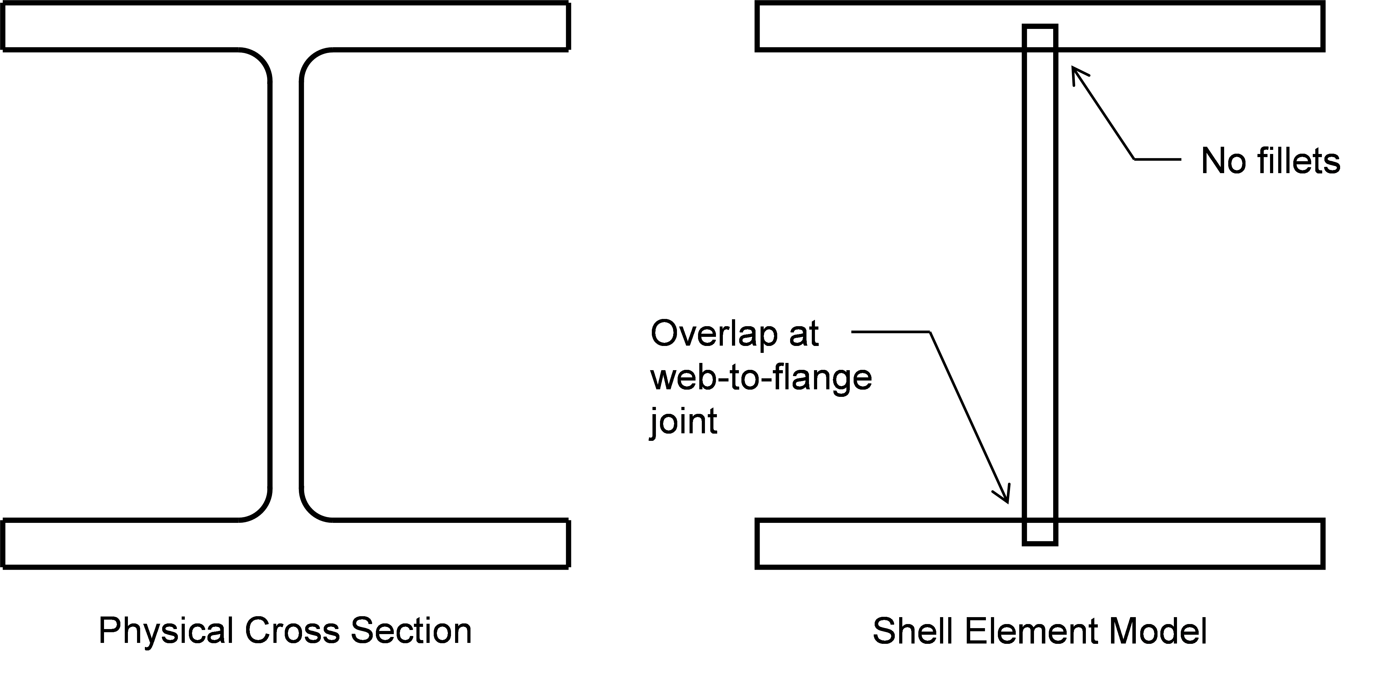
Los elementos de acero estructural se modelan con elementos de lámina en IDEA StatiCa, lo que conlleva algunas simplificaciones de la geometría física. Los elementos de lámina solo representan componentes rectangulares, por lo que los acuerdos se desprecian. Además, dado que los elementos de lámina se conectan en nodos situados en el centro del espesor, existe cierta superposición en las uniones de los elementos de la sección transversal. La figura siguiente muestra las simplificaciones para un perfil de ala ancha. Las simplificaciones provocan pequeñas diferencias en el área de la sección transversal que pueden afectar a la resistencia a la plastificación por tracción. Para un W14x159, el área de la sección transversal indicada en la Tabla 1-1 del Manual AISC es de 46,7 pulg.2. El área de la sección transversal cuando se modela como en IDEA StatiCa es 2bftf+(d-tf)tw = 2(15,6 pulg.)(1,19 pulg.) + (15,0 pulg. – 1,19 pulg.)(0,745 pulg.) = 47,4 pulg.2, donde las dimensiones de la sección transversal también se obtuvieron de la Tabla 1-1 del Manual AISC. Esto supone una diferencia del 1,5%.
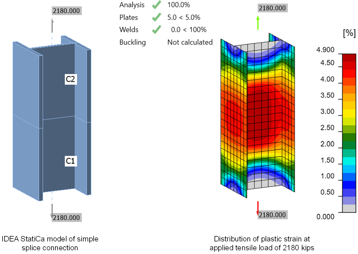
El efecto global de estas diferencias menores puede observarse en un modelo sencillo de IDEA StatiCa de una unión de empalme entre dos perfiles de acero W14x159 (ASTM A992). El empalme está soldado a tope (p. ej., CJP) y cargado a tracción. Según la Especificación AISC (2022), la resistencia de cálculo del elemento de ala ancha a tracción es 0,9×(50 ksi)×(46,7 pulg.2) = 2.100 kips. La carga máxima que puede aplicarse a la unión en IDEA StatiCa (versión 22.1) es de 2.180 kips, un 4% mayor que la resistencia de cálculo calculada según la Especificación AISC. La distribución de la deformación plástica en la unión muestra que la sección transversal completa ha plastificado.
Rotura a Tracción
Las disposiciones para el estado límite de rotura a tracción se encuentran en el Capítulo D de la Especificación AISC. Estas disposiciones se referencian en la Sección J4.1 de la Especificación AISC para los elementos de conexión. La resistencia nominal a la rotura por tracción se calcula como la resistencia a tracción del material, Fu, multiplicada por el área neta efectiva, Ae. El área neta efectiva tiene en cuenta el material eliminado, incluidos los orificios de los pernos, y el efecto del retraso al cortante mediante el factor de retraso al cortante, U, definido en la Tabla D3.1 de la Especificación AISC. Se aplica un factor de resistencia de ϕ = 0,75 a la resistencia nominal para determinar la resistencia de cálculo.
El estado límite de rotura a tracción no se evalúa directamente en IDEA StatiCa. Se contempla limitando la cantidad de deformación plástica que puede experimentar cualquier componente. El límite de deformación plástica predeterminado en IDEA StatiCa es del 5%. Ni Fu ni el factor de resistencia de ϕ = 0,75 se utilizan en IDEA StatiCa. IDEA StatiCa utiliza una relación tensión-deformación bilineal en la que la plastificación se produce a la tensión de fluencia del acero, Fy, multiplicado por un factor de reducción igual a 0,9 por defecto (el usuario puede ajustar este factor). Tras la plastificación, la rigidez del acero es solo una milésima parte del módulo de elasticidad. Esta rigidez post-plastificación se incluye por estabilidad numérica y no proporciona ningún endurecimiento por deformación significativo. Además, IDEA StatiCa no utiliza los factores de retraso al cortante de la Tabla D3.1 de la Especificación AISC. En su lugar, el retraso al cortante se modela explícitamente.
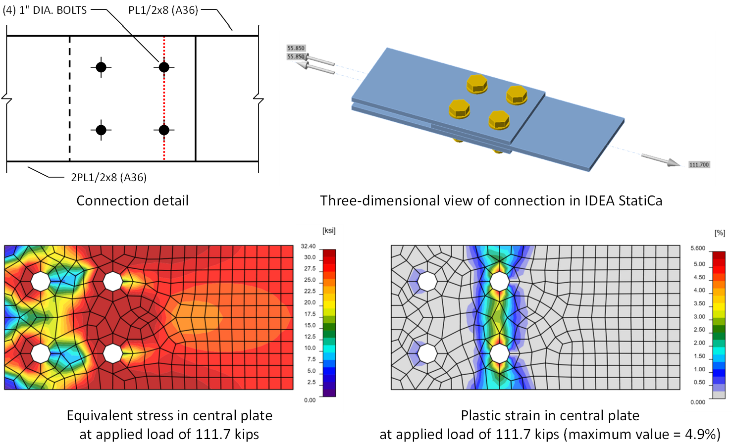
Además, las tensiones que se desarrollan en las regiones de unión raramente son puramente uniaxiales. IDEA StatiCa utiliza el criterio de plastificación de von Mises para identificar cuándo se produce la plastificación bajo estos estados de tensión complejos, lo que puede dar lugar a un aparente incremento de resistencia. Para ilustrar este efecto, considérese la unión de empalme simple mostrada en la figura siguiente. La resistencia de la placa central cerca de los pernos controla la resistencia de esta unión. Basándose en los procedimientos de cálculo manual, podría esperarse que la resistencia que determinará IDEA StatiCa sea la tensión a la que se produce la plastificación multiplicada por el área neta (indicada por una línea de puntos roja en la figura). Para esta unión, el área neta es (1/2 pulg.)×(8 pulg. – 2dh) = 2,875 pulg.2, donde el diámetro del orificio, dh, es igual a 1-1/8 pulg. (nótese que IDEA StatiCa no incluye las 1/16 pulg. por daño descritas en la Sección B4.3b de la Especificación AISC; véase la entrada sobre Determinación del Área Neta para información adicional - ADD ANCHOR). Para LRFD, la tensión a la que se produce la plastificación en IDEA StatiCa es 0,9Fy y el endurecimiento por deformación es mínimo (véase la entrada sobre Plastificación a Tracción para información adicional). Para el material A36 utilizado en este ejemplo, la plastificación se producirá a 0,9(36 ksi) = 32,4 ksi. Por lo tanto, podría esperarse que la resistencia de esta unión en IDEA StatiCa fuera (2,875 pulg.2)×(32,4 ksi) = 93,1 kips. Sin embargo, dado que la tensión no es puramente uniaxial en la sección neta, los demás componentes de tensión aumentan efectivamente la tensión de fluencia normal al área neta, y la deformación plástica del 5% no se alcanza hasta una carga aplicada de 111,7 kips.
Consideradas individualmente, las diferencias entre los cálculos tradicionales e IDEA StatiCa resultan en resistencias menores en IDEA StatiCa (utilizando solo Fy y no Fu), resistencias mayores en IDEA StatiCa (utilizando un factor de reducción de resistencia del material de 0,9 en lugar de ϕ = 0,75), y resistencias diferentes según la unión específica (modelando explícitamente el retraso al cortante en lugar de utilizar el factor de retraso al cortante, U). Consideradas en conjunto, las diferencias generalmente, aunque no siempre, resultan en una resistencia igual o menor de IDEA StatiCa que la obtenida con los cálculos tradicionales.
El estado límite de rotura a tracción fue investigado en este estudio mediante comparación con cientos de resultados experimentales. Los resultados muestran que IDEA StatiCa es generalmente conservador, especialmente a nivel de resistencia nominal, aunque hay algunos casos en los que la resistencia disponible de IDEA StatiCa es mayor que la calculada según la Especificación AISC. Utilizando propiedades materiales y geométricas medidas sin factores de resistencia aplicados, la resistencia de IDEA StatiCa fue menor o igual a la resistencia observada experimentalmente para todos los especímenes excepto 12 de 529 (9 de los cuales fueron fabricados con acero de alta resistencia, Fy = 122,8 ksi) y menor o igual a la resistencia esperada a la rotura por tracción calculada mediante ecuaciones de diseño para todos los especímenes excepto 30 de 529. Utilizando propiedades materiales y geométricas nominales con factores de resistencia aplicados, se encontró que la resistencia de IDEA StatiCa era mayor que la resistencia calculada según la Especificación AISC para algunas uniones sin contrapartida física, especialmente elementos de placa a tracción con soldaduras relativamente cortas y elementos de HSS rectangular a tracción. Dado que los datos experimentales para estos casos son limitados, se está trabajando para determinar si las diferencias son resultado de un comportamiento no conservador en IDEA StatiCa o de conservadurismo en las ecuaciones de la Especificación AISC.
Plastificación y Pandeo a Compresión
La resistencia disponible de los elementos afectados de los elementos estructurales y los elementos de conexión a compresión se define en la Sección J4.4 de la Especificación AISC. Cuando la esbeltez, Lc/r, es menor o igual a 25, se aplica la plastificación a compresión y la resistencia nominal se calcula como el producto del límite elástico mínimo especificado y el área bruta (es decir, Pn = FyAg). Al igual que para la Plastificación a Tracción, el estado límite de plastificación a compresión se evalúa en IDEA StatiCa con el límite de deformación plástica del 5%.
Cuando la esbeltez, Lc/r, es mayor que 25, se aplican las disposiciones del Capítulo E de la Especificación AISC. Los estados límite del Capítulo E de la Especificación AISC incluyen el pandeo por flexión, el pandeo torsional y el pandeo flexotorsional. El análisis no lineal realizado en IDEA StatiCa es no lineal porque incluye efectos como la plastificación y el contacto. El análisis generalmente no considera no linealidades geométricas como los efectos P-Δ (las no linealidades geométricas se consideran cuando se utilizan perfiles HSS como elementos de apoyo).
Los ingenieros también deben realizar un análisis lineal de pandeo para detectar el pandeo. Un análisis lineal de pandeo puede determinar la carga de pandeo elástico, expresada como una relación respecto a la carga aplicada. Aunque proporciona información útil que puede orientar el diseño, el análisis lineal de pandeo no considera la posible plastificación que puede reducir la rigidez y la carga de pandeo (es decir, el pandeo inelástico), ni considera los efectos de las imperfecciones geométricas iniciales. Debido a estas limitaciones, para utilizar IDEA StatiCa, la unión debe ser suficientemente robusta para que no se produzca ni el pandeo elástico ni el inelástico. La relación de carga de pandeo elástico proporciona una medida conveniente de la robustez (o esbeltez).
Considérese el límite de esbeltez de la Sección J4.4 de la Especificación AISC de Lc/r ≤ 25 para asumir plastificación a compresión. Una esbeltez de Lc/r = 25 corresponde a una tensión crítica elástica Fe = π2E/(Lc/r)2 = π2(29.000 ksi)/(25)2 = 458 ksi. Para acero A36, esto corresponde a 14 veces la tensión de fluencia mayorada para LRFD y 21 veces la tensión de fluencia mayorada para ASD. Para acero de grado 50, la tensión crítica elástica corresponde a 10 veces la tensión de fluencia mayorada para LRFD y 15 veces la tensión de fluencia mayorada para ASD. En consecuencia, la relación de carga de pandeo elástico debe mantenerse por encima de estas relaciones para evitar casos en los que el pandeo inelástico pueda ser determinante.
El límite apropiado para la relación de carga de pandeo elástico varía según la configuración de la unión. Para el pandeo de placas, el límite es mucho menor. Basándose en los límites de esbeltez de la Tabla B4.1a de la Especificación AISC, la relación de carga de pandeo crítico elástico debe mantenerse en no menos de 3 para LRFD y 4,5 para ASD. Una evaluación de placas de ménsula identificó límites de relación de carga de pandeo crítico elástico de 4 para LRFD y 6 para ASD. El uso de un límite de relación de carga de pandeo crítico de 3 ha sido evaluado para rigidizadores de apoyo (informe próximamente), vigas con extremo rebajado y uniones de viga sobre pilar.
Los elementos de uniones con esbeltez suficiente para que se produzca el pandeo inelástico siguen teniendo resistencia, potencialmente suficiente para una aplicación determinada. Sin embargo, sin la capacidad de cuantificar con precisión la resistencia al pandeo inelástico en IDEA StatiCa, estos casos deben evitarse.
Plastificación y Rotura a Cortante
La resistencia disponible de los elementos afectados de los elementos estructurales y los elementos de conexión a cortante se define en la Sección J4.2 de la Especificación AISC. Esta sección describe dos estados límite: plastificación a cortante y rotura a cortante. Para ambos estados límite, IDEA StatiCa no calcula la resistencia disponible según la Especificación AISC, sino que se basa en el límite de deformación plástica del 5% para evaluar si la unión tiene resistencia suficiente.
A tracción, la relación tensión-deformación utilizada en IDEA StatiCa es lineal hasta la plastificación, con una rigidez igual al módulo de elasticidad, y lineal a partir de entonces, con una rigidez igual a una milésima parte del módulo de elasticidad. La plastificación a tracción se produce al límite elástico mínimo especificado del acero, Fy, multiplicado por 0,9 para LRFD o dividido por 1,67 para ASD. IDEA StatiCa utiliza el criterio de plastificación de von Mises para determinar cuándo comienza la plastificación bajo estados de tensión multiaxiales. Según el criterio de plastificación de von Mises, el material sometido a cortante puro plastificará cuando la tensión tangencial sea igual a la tensión de fluencia dividida por la raíz cuadrada de 3. El inverso de la raíz cuadrada de 3 es aproximadamente igual a 0,577, lo que es aproximadamente igual al factor 0,6 aplicado a las ecuaciones de resistencia a cortante en la Especificación AISC. Esta diferencia, o diferencias similares cuando el elemento no está estrictamente en cortante puro, puede dar lugar a diferencias entre IDEA StatiCa y los cálculos tradicionales. La pequeña cantidad de endurecimiento por deformación también puede dar lugar a diferencias, tal como se describe en la entrada sobre Plastificación a Tracción.
También pueden surgir diferencias porque en la Sección J4.2 de la Especificación AISC, el factor de resistencia para la plastificación a cortante se define como 1,00 y el coeficiente de seguridad para la plastificación a cortante se define como 1,50. IDEA StatiCa no utiliza estos factores y en su lugar reduce el límite elástico por un factor de 0,9 para LRFD o dividiéndolo por 1,67 para ASD, basándose en el factor de resistencia y el coeficiente de seguridad típicos para la plastificación.
Existen otras diferencias para el estado límite de rotura a cortante. Como se describe para el estado límite de Rotura a Tracción, IDEA StatiCa no utiliza la resistencia a tracción del acero, Fu, ni el factor de resistencia o el coeficiente de seguridad para la rotura a cortante. De nuevo, el límite elástico a tracción se toma como 0,9Fy para LRFD y Fy/1,67 para ASD. El resultado de estas diferencias depende de la relación entre las resistencias del material. También en las uniones atornilladas, el área neta sometida a cortante pasa típicamente por las líneas de centro de los pernos. La distribución de las deformaciones plásticas en el punto límite en IDEA StatiCa puede ser diferente, como se observó para las uniones de placa de aleta simple en este artículo.
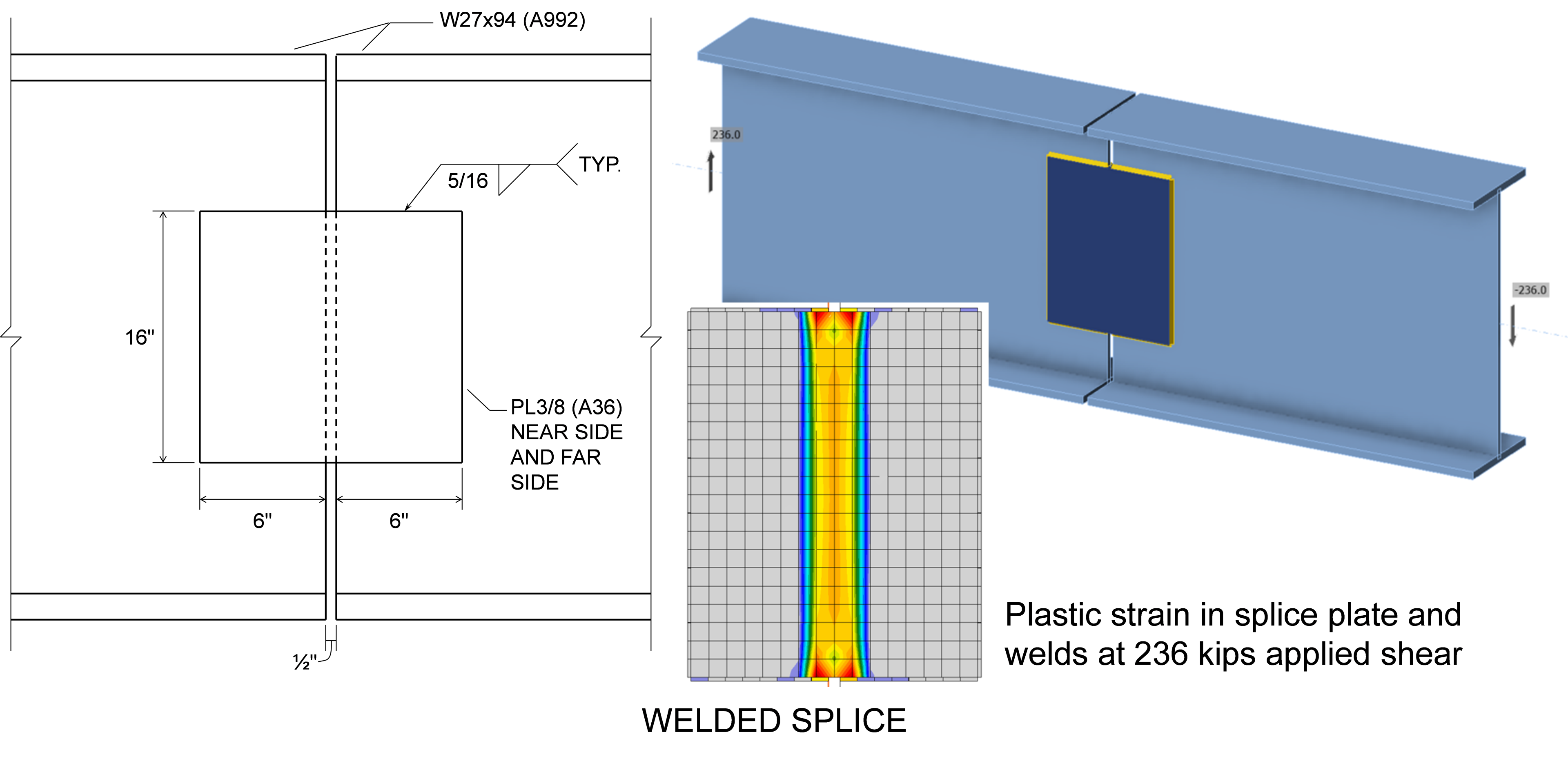
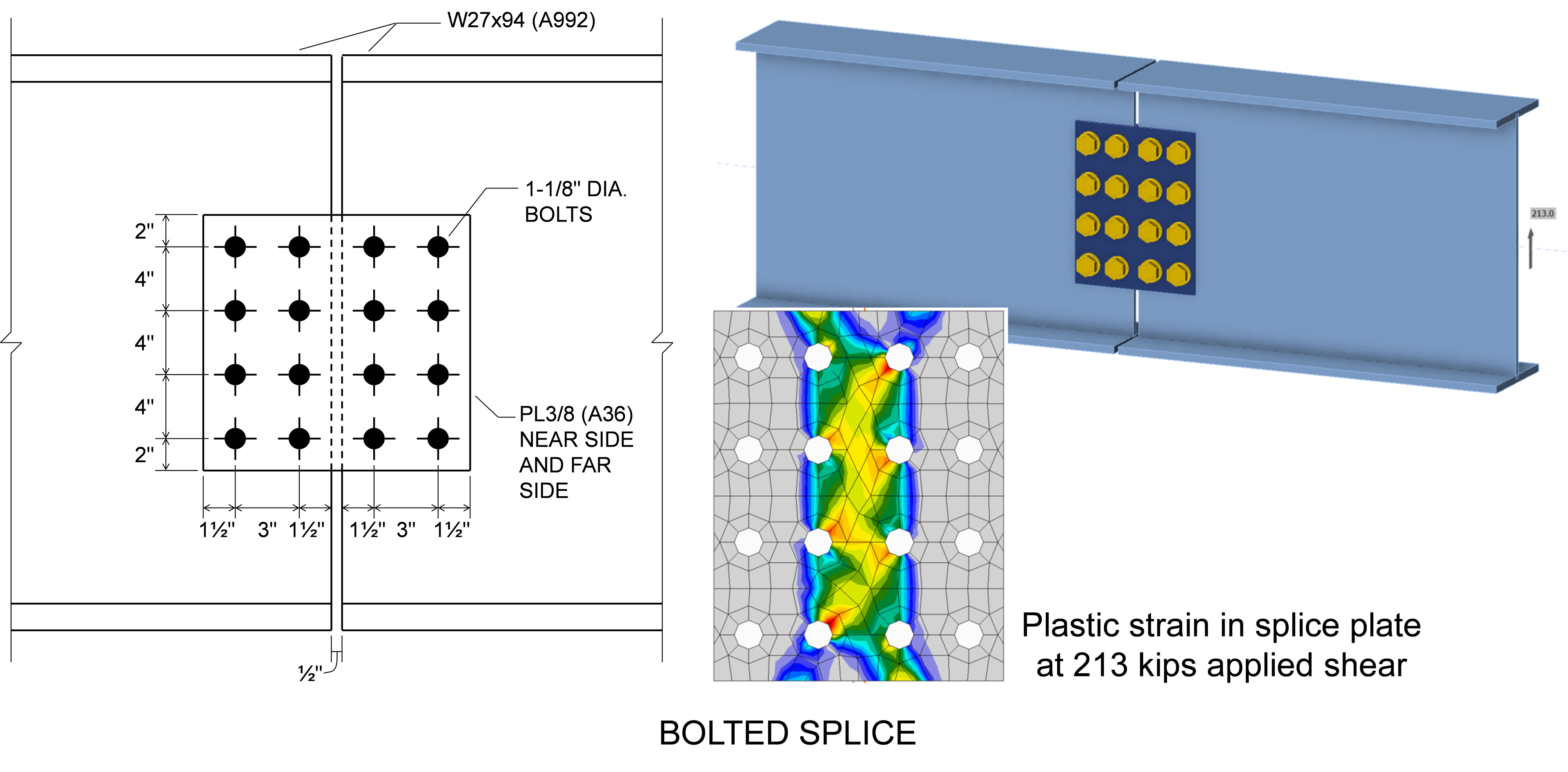
Como ejemplo del resultado combinado de las diferencias entre las ecuaciones de la Especificación AISC e IDEA StatiCa, considérense las dos uniones de empalme de viga mostradas en las figuras siguientes. En ambas, dos vigas W27×94 de acero A992 están conectadas mediante placas de empalme a ambos lados del alma. Las placas de empalme tienen un espesor de 3/8 pulg. y están fabricadas con acero A36.
La unión soldada está controlada por la plastificación a cortante de las placas de empalme. La resistencia de cálculo de las placas es ϕRn = ϕ0,6FyAgv = (1,0)0,6(36 ksi)(2 × 3/8 pulg. × 16 pulg.) = 259 kips. En IDEA StatiCa, las placas de empalme alcanzan una deformación plástica del 5% cuando están sometidas a una carga cortante de 236 kips. La diferencia de resistencias se debe principalmente al uso de ϕ = 1,0 en las ecuaciones de la Especificación AISC y a una reducción de 0,9 sobre la tensión de fluencia en IDEA StatiCa.
La unión atornillada está controlada por la rotura a cortante de las placas de empalme. La resistencia de cálculo de las placas es ϕRn = 210 kips. En IDEA StatiCa, las placas de empalme alcanzan una deformación plástica del 5% cuando están sometidas a una carga cortante de 213 kips, prácticamente igual a la resistencia de cálculo según la Especificación AISC, lo que indica que las diferencias se compensan entre sí y resultan en un diseño seguro.
Plastificación bajo Acciones Combinadas
Los elementos estructurales y los elementos de conexión están frecuentemente sometidos a múltiples acciones simultáneamente, incluyendo fuerza axial, momento flector, cortante y torsión. La Sección J4 de la Especificación AISC no proporciona requisitos específicos para los elementos de conexión sometidos a acciones combinadas. Sin embargo, la Parte 9 del Manual AISC describe varios enfoques para evaluar los elementos de conexión sometidos a acciones combinadas. Un enfoque consiste en superponer las tensiones calculadas basándose en la teoría elástica de vigas y utilizar un criterio de primera plastificación. Otro enfoque consiste en utilizar ecuaciones de interacción que aproximan el límite de resistencia plástica. Una de estas ecuaciones, aplicable a elementos rectangulares bajo carga en el plano, es la Ecuación 9-1 del Manual AISC.
\[ \frac{M_r}{M_c} + \left ( \frac{P_r}{P_c} \right )^2 + \left ( \frac{V_r}{V_c} \right )^4 \le 1.0 \]
donde Mr, Pr y Vr son las resistencias requeridas a flexión, axial y cortante, respectivamente; y Mc, Pc y Vc son las resistencias disponibles a flexión, axial y cortante, respectivamente.
Dowswell (2015) presentó una ecuación más general para elementos rectangulares bajo carga en el plano y fuera del plano.
\[ \left ( \frac{P_r}{P_c} \right )^2 + \left ( \frac{T_r}{T_c} \right )^2 + \left ( \frac{V_r}{V_c} \right )^4 + \left ( \left ( \frac{M_{rx}}{M_{cx}} \right )^{1.7} + \left ( \frac{M_{ry}}{M_{cy}} \right )^{1.7} \right )^{0.59} \le 1.0 \]
donde Tr, Mrx y Mry son las resistencias requeridas a torsión, flexión en el eje principal y flexión en el eje secundario, respectivamente; y Tc, Mcx y Mcy son las resistencias disponibles a torsión, flexión en el eje principal y flexión en el eje secundario, respectivamente.
En IDEA StatiCa, los elementos de conexión se modelan con elementos finitos de lámina a los que se asigna un modelo de material de plasticidad multiaxial que utiliza el criterio de plastificación de von Mises (el uso del criterio de plastificación de von Mises también se describe en la Parte 9 del Manual AISC). A medida que se aplica la carga en el modelo, los elementos de lámina individuales experimentan estados generales de tensión que se evalúan mediante el criterio para determinar si se ha producido la plastificación. Si se produce la plastificación, la rigidez del material se reduce a 1/1000 de la rigidez inicial y el análisis continúa.
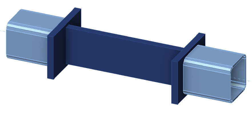
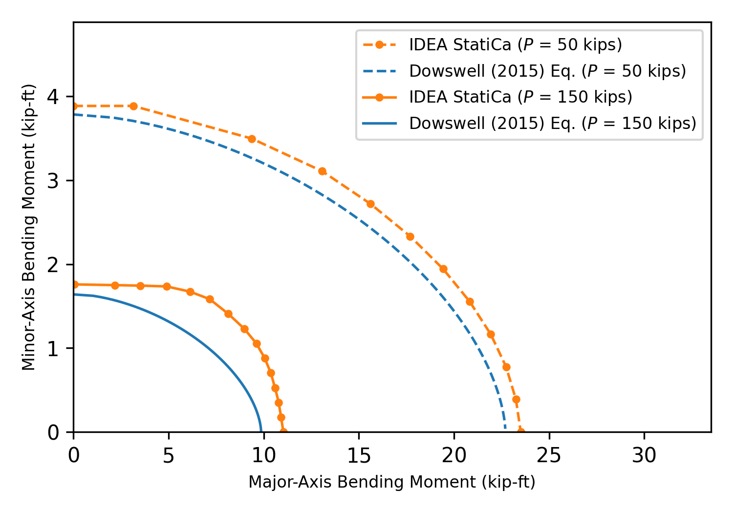
Para ilustrar las diferencias entre las resistencias calculadas mediante ecuaciones de interacción e IDEA StatiCa, considérese la unión mostrada a continuación. La placa central de "ensayo" tiene un espesor de 1 pulg., una altura de 6 pulg., una longitud de 10 pulg. y está fabricada con acero A36. Tanto las placas de conexión como los elementos de sección hueca se seleccionaron para ser resistentes y rígidos. Se realizaron análisis sometiendo la placa de ensayo a carga biaxial, consistente en tracción axial y momento flector en torno a los ejes principal y secundario, para determinar las cargas aplicadas máximas permitidas (es decir, las cargas que provocan una deformación plástica del 5% en la placa de ensayo). Para estos análisis, la opción geométrica no lineal (GMNA) se desactivó en la configuración de código. Además, el tamaño máximo de los elementos se cambió a 0,25 pulg. y el tamaño mínimo de los elementos se cambió a 0,10 pulg. para crear una malla más fina y capturar la distribución de tensiones con mayor precisión.
Los resultados de los análisis de IDEA StatiCa se muestran en la figura siguiente. En la figura también se muestran los diagramas de interacción basados en la ecuación de Dowswell (2015). Las resistencias disponibles utilizadas para los diagramas de interacción calculados son Pc = ϕPn = 194,4 kips, Mcx = ϕMnx = 24,3 kip-ft y Mcy = ϕMny = 4,05 kip-ft. Se observan diferencias entre los resultados de IDEA StatiCa y los de la ecuación de interacción, incluso cuando solo se aplica una acción. Las causas de las diferencias bajo una única acción se describen en las entradas sobre plastificación a flexión y plastificación a tracción. Las diferencias entre IDEA StatiCa y la ecuación aproximada para acciones combinadas son mayores, pero los resultados de IDEA StatiCa muestran claros efectos de interacción.
Rotura por Bloque de Cortante
La rotura por bloque de cortante es un fallo combinado de tracción y cortante en el que un bloque de material se desprende de un elemento estructural o de un elemento de conexión. La resistencia disponible para el estado límite de rotura por bloque de cortante se define en la Sección J4.3 de la Especificación AISC. Al igual que con el estado límite de rotura a tracción, el estado límite de rotura por bloque de cortante no se evalúa directamente en IDEA StatiCa. Se contempla limitando la cantidad de deformación plástica que puede experimentar cualquier componente a un máximo del 5% (el usuario puede cambiar este límite). Las diferencias clave entre los cálculos tradicionales e IDEA StatiCa resultan de la relación tensión-deformación utilizada en IDEA StatiCa. Solo se incluye un endurecimiento post-plastificación mínimo (es decir, las tensiones no alcanzan Fu), y la tensión de fluencia se reduce en 0,9 para LRFD (es decir, no ϕ = 0,75 como se especifica para la rotura por bloque de cortante).
En este artículo se presenta una comparación entre los cálculos tradicionales e IDEA StatiCa para el estado límite de rotura por bloque de cortante en uniones atornilladas. Los resultados de la comparación muestran que la resistencia de IDEA StatiCa puede ser mayor que la obtenida según la Especificación AISC en algunos casos, especialmente si la relación entre la resistencia a tracción y la tensión de fluencia (Fu/Fy) es relativamente baja. Sin embargo, los investigadores han identificado que las disposiciones de la Especificación AISC pueden ser conservadoras en comparación con los resultados experimentales. Se encontró que la resistencia a la rotura por bloque de cortante de IDEA StatiCa era precisa o conservadora en comparación con la norma canadiense (CSA S16) y una ecuación de diseño alternativa propuesta por investigadores.
La resistencia para el estado límite de rotura por bloque de cortante en IDEA StatiCa puede variar según el tipo de transmisión de fuerza cortante de los pernos. En IDEA StatiCa, las fuerzas se transmiten de una placa a otra sobre un área mayor para las uniones resistentes al deslizamiento que para las uniones de tipo aplastamiento. La mayor distribución de las fuerzas de transmisión, aunque físicamente representativa de la transmisión de carga por fricción, puede dar lugar a diferentes trayectorias de fallo por rotura de bloque de cortante y a una mayor resistencia. En la mayoría de las uniones, la resistencia al deslizamiento es menor que la resistencia a la rotura por bloque de cortante. Sin embargo, dado que las uniones resistentes al deslizamiento deben diseñarse también para los estados límite de las uniones de tipo aplastamiento además del deslizamiento (Sección J3.9 de la Especificación AISC), se recomienda analizar las uniones resistentes al deslizamiento dos veces en IDEA StatiCa: una como unión resistente al deslizamiento (es decir, con el tipo de transmisión de fuerza cortante configurado como "Fricción") y otra como unión de tipo aplastamiento (es decir, con el tipo de transmisión de fuerza cortante configurado como "Aplastamiento – interacción tracción/cortante").
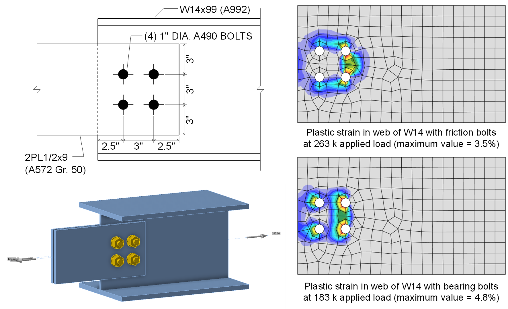
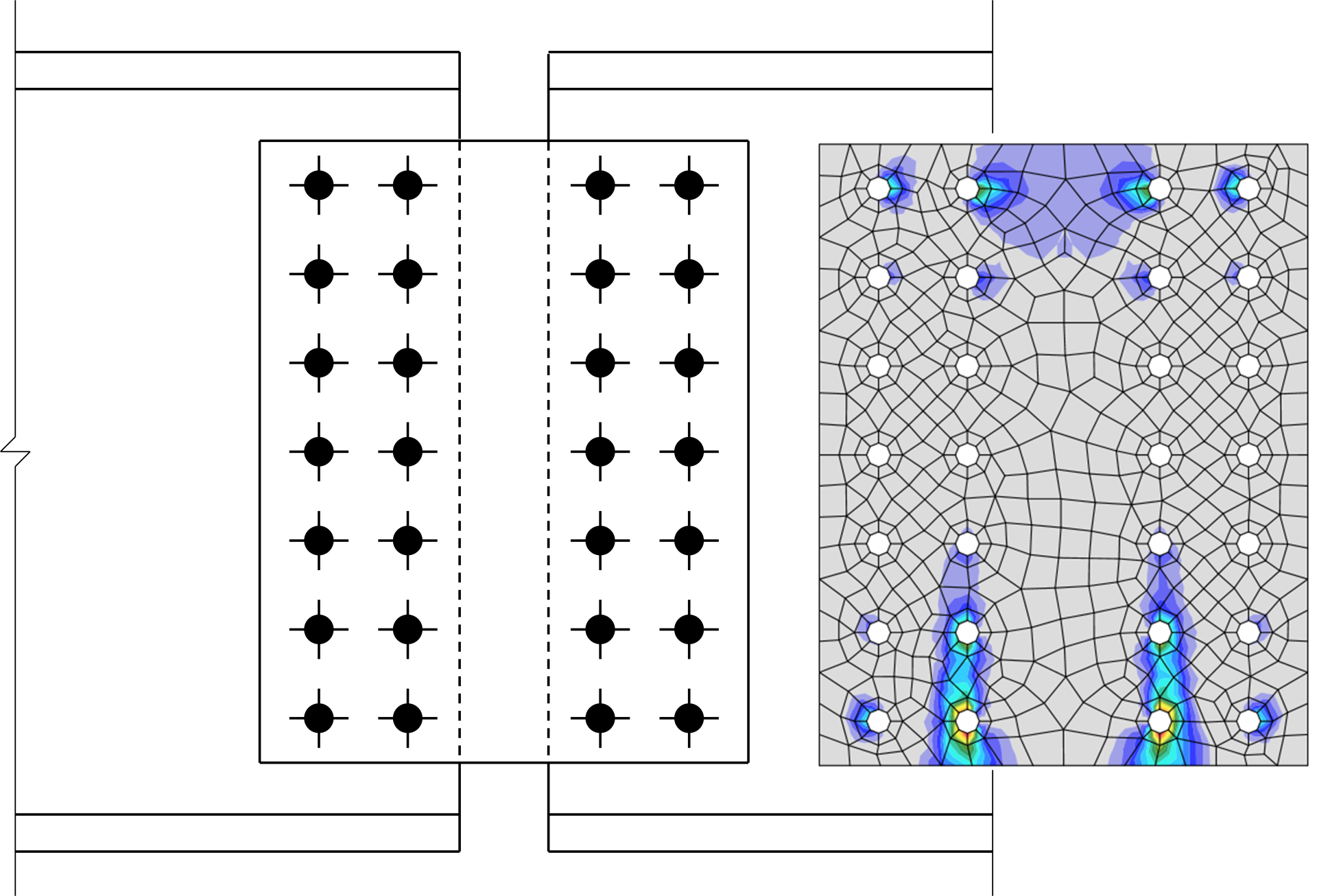
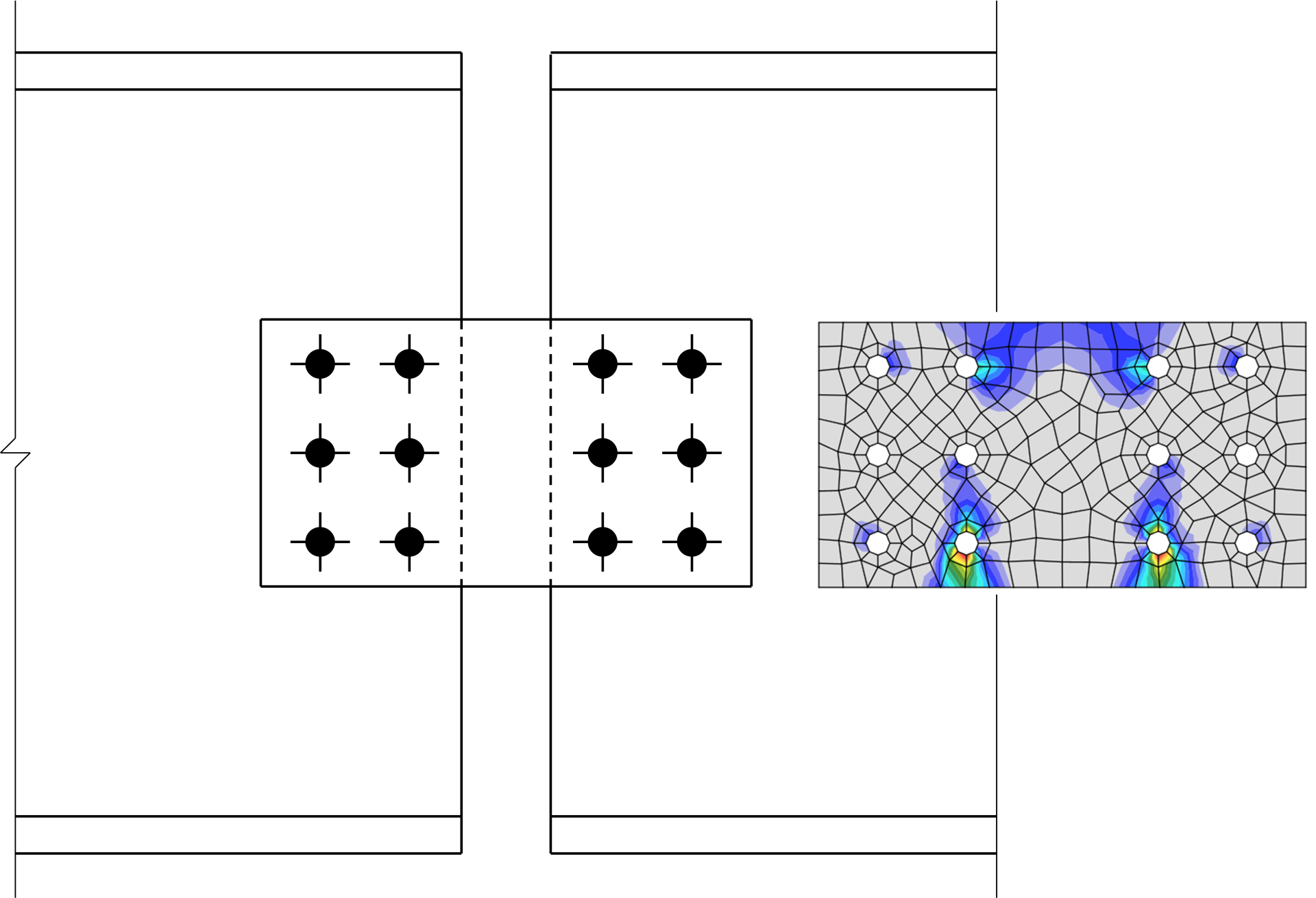
Para ilustrar este efecto, considérese la unión mostrada a continuación entre un elemento a tracción W14x99 (A992) y dos placas. La unión se realiza con (4) pernos A490 de 1 pulg. de diámetro en orificios estándar y superficies de Clase B. La resistencia de cálculo de esta unión para el estado límite de deslizamiento es \(\phi R_n = 289\textrm{ kips}\); sin embargo, la rotura por bloque de cortante controla la resistencia de la unión con una resistencia de cálculo de \(\phi R_n = 148 \textrm{ kips}\). Cuando se modela en IDEA StatiCa y el tipo de transmisión de fuerza cortante de los pernos se configura como "Fricción", pueden aplicarse cargas de hasta 263 kips antes de que la utilización de los pernos alcance el 100%. La diferencia entre esta resistencia y la resistencia de cálculo de 289 kips para el estado límite de deslizamiento se debe a que la tracción en los pernos se desarrolla en el modelo y se trata de forma conservadora como una tracción aplicada en IDEA StatiCa. Con 263 kips de tracción aplicada y utilizando pernos de "Fricción", la deformación plástica en el alma es del 3,5%, por debajo del límite del 5%. Cuando el tipo de transmisión de fuerza cortante de los pernos se configura como "Aplastamiento – interacción tracción/cortante", la carga aplicada máxima disminuye a 183 kips, siendo la deformación plástica en el alma la que controla. La diferencia entre esta resistencia y la resistencia de cálculo de 148 kips para el estado límite de rotura por bloque de cortante es predominantemente el conservadurismo en la ecuación de la Especificación AISC para la rotura por bloque de cortante, tal como se describe en este artículo. Según la norma canadiense (CSA S16), la resistencia de cálculo de esta unión para el estado límite de rotura por bloque de cortante es de 181 kips, aproximadamente igual a la resistencia de IDEA StatiCa. La figura siguiente muestra la deformación plástica en el alma a la carga aplicada máxima para cada tipo de transmisión de fuerza cortante. Las distribuciones de deformación plástica son claramente diferentes y demuestran la mayor distribución de fuerzas de transmisión para los pernos de "Fricción" en IDEA StatiCa. Se puede encontrar información adicional en la entrada sobre Deslizamiento.
Plastificación a Flexión
La resistencia nominal a la plastificación por flexión se define en el Capítulo F de la Especificación AISC (2022) para elementos a flexión y en la Sección J4.5 para elementos de conexión. La resistencia nominal para el estado límite de plastificación a flexión se toma generalmente como el límite elástico mínimo especificado, Fy, multiplicado por el módulo resistente plástico, Z. En IDEA StatiCa, en lugar de limitar la resistencia requerida a no más que la resistencia disponible (p. ej., Mu ≤ ϕMn), los elementos estructurales y los elementos de conexión se modelan con elementos de lámina a los que se asigna una relación tensión-deformación no lineal compuesta por una región elástica lineal y una región plástica lineal, y la deformación plástica se limita al 5%.
El modelado de elementos estructurales y elementos de conexión como elementos de lámina conlleva algunas simplificaciones de la geometría física. Por ejemplo, los elementos de lámina solo representan componentes rectangulares, por lo que los acuerdos se desprecian. Además, dado que los elementos de lámina se conectan en nodos situados en el centro del espesor, existe cierta superposición en las uniones de los elementos de la sección transversal. La figura siguiente muestra las simplificaciones para un perfil de ala ancha.

Perfil de ala ancha tal como se modela en IDEA StatiCa
Para un W24x176, el módulo resistente plástico respecto al eje principal (eje x) indicado en la Tabla 1-1 del Manual de Construcción en Acero AISC (2023) es de 511 pulg.3. El módulo resistente plástico respecto al eje principal de la sección transversal formada por los elementos de lámina (con dimensiones de la sección transversal determinadas a partir de la Tabla 1-1 del Manual AISC) se calcula de la siguiente manera:
\[\frac{t_w(d-t_f)^2}{4}+2b_f t_f \left ( \frac{d-t_f}{2} \right ) = \frac{0.75 \textrm{ in.}(25.2 \textrm{ in.}-1.34\textrm{ in.})^2}{4}+2(12.9\textrm{ in.}) (1.34\textrm{ in.}) \left ( \frac{25.2\textrm{ in.}-1.34\textrm{ in.}}{2} \right ) = 519.2 \textrm{ in.}^3\]
Esto es un 1,6% mayor que el módulo resistente plástico indicado en la tabla del Manual AISC.
La distribución de tensiones en el límite de deformación plástica en IDEA StatiCa también será diferente de la distribución de tensiones idealizada utilizada para calcular Mp. A diferencia de la distribución de tensiones idealizada, las tensiones serán inferiores a Fy cerca del eje neutro, ya que el límite de deformación plástica se alcanzará a una curvatura finita. Además, las tensiones serán superiores a Fy en las fibras extremas de la sección transversal porque en la relación tensión-deformación de IDEA StatiCa se asume una pequeña cantidad de endurecimiento post-plastificación.
El efecto global de estas diferencias menores puede observarse en una unión de empalme simple entre dos perfiles de acero W24x176 (ASTM A992). El empalme está soldado a tope (p. ej., CJP) y cargado en flexión respecto al eje principal. La resistencia de cálculo del perfil de ala ancha según la Especificación AISC (2022) con factor de resistencia, ϕ = 0,9, es 0,9 × 50 ksi × 511 pulg.3 = 1916,3 kip-ft. El momento máximo que puede aplicarse a la unión en IDEA StatiCa (versión 23.0) es de 2000,7 kip-ft, un 4,4% mayor que la resistencia de cálculo calculada según la Especificación AISC. La distribución de deformación plástica en el límite se muestra en la figura siguiente. Como era de esperar, las alas superior e inferior han plastificado, pero el alma en el eje neutro permanece elástica.
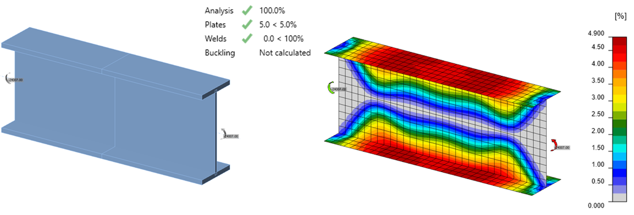
Distribución de deformación plástica para un elemento a flexión W24x176 en el límite de deformación plástica del 5%
La relación entre el momento aplicado y la deformación plástica máxima se muestra en la figura siguiente. La resistencia a flexión de cálculo calculada utilizando el módulo resistente plástico del Manual AISC se muestra como ϕMp (Manual). La resistencia a flexión de cálculo calculada utilizando el módulo resistente plástico calculado como se muestra anteriormente, basándose en la representación de la sección en IDEA StatiCa, se muestra como ϕMp (IDEA).
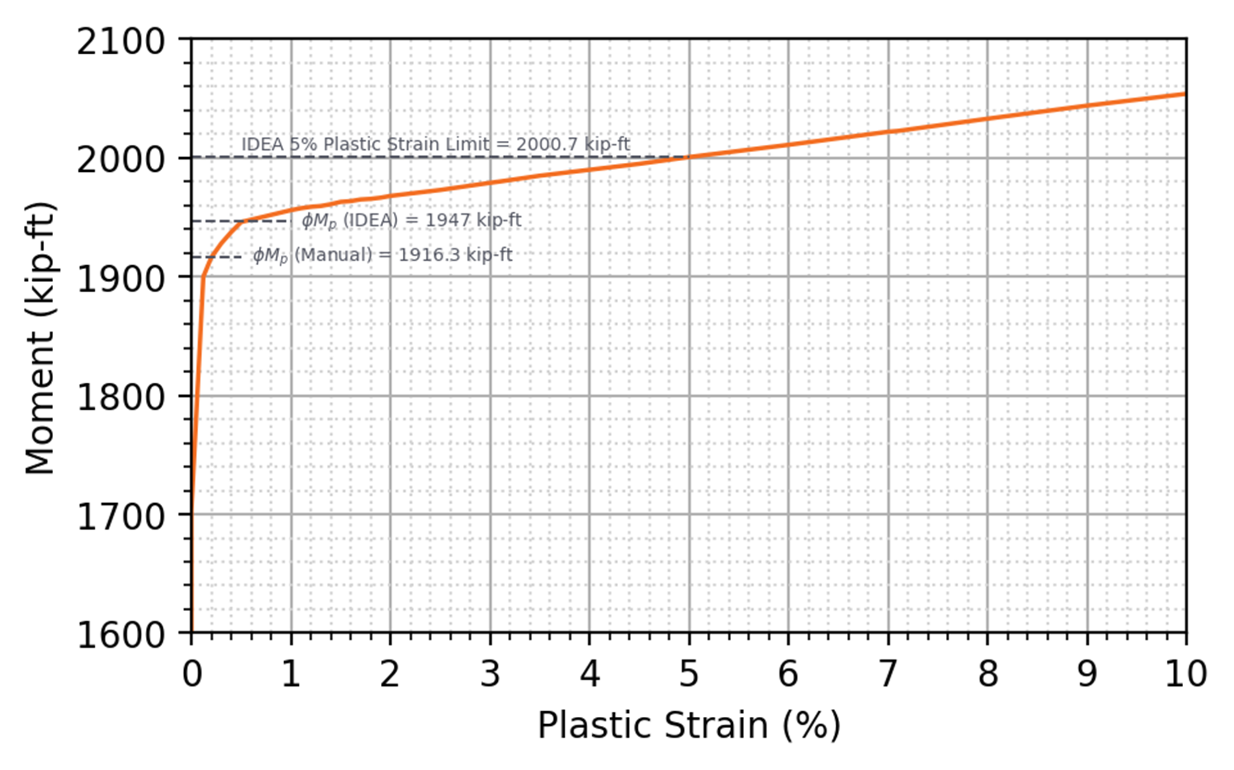
Momento aplicado frente a deformación plástica para un elemento a flexión W24x176
Para una viga de ala ancha, la mayor parte de la resistencia a flexión se captura mediante el comportamiento en el plano de los elementos de lámina. El comportamiento fuera del plano de los elementos de lámina puede evaluarse mediante una investigación de la flexión de placas.
Para una placa (ASTM A36, Fy = 36 ksi) de anchura, b = 10 pulg. y espesor, t = 0,5 pulg., el módulo resistente plástico para flexión fuera del plano se calcula como Z = bt2/4 = 0,625 pulg.3, y la resistencia de cálculo, ϕMp, con factor de resistencia, ϕ = 0,9, se calcula como 0,9 × 36 ksi × 0,625 pulg.3 = 20,25 kip-pulg. Las simplificaciones geométricas descritas anteriormente para una sección de ala ancha no se aplican a una placa rectangular simple, pero persisten diferencias en la distribución de tensiones. El momento máximo que puede aplicarse a la placa en IDEA StatiCa (versión 23.0) es de 19,66 kip-pulg., un 2,9% menor que la resistencia de cálculo calculada según la Especificación AISC. La distribución de deformación plástica para la placa cargada en flexión respecto al eje secundario y un gráfico del momento aplicado frente a la deformación plástica se presentan en las figuras siguientes.
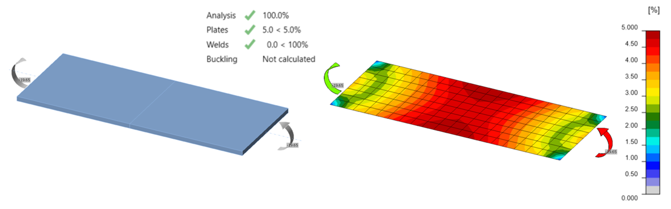
Distribución de deformación plástica para flexión fuera del plano de una placa en el límite de deformación plástica del 5%
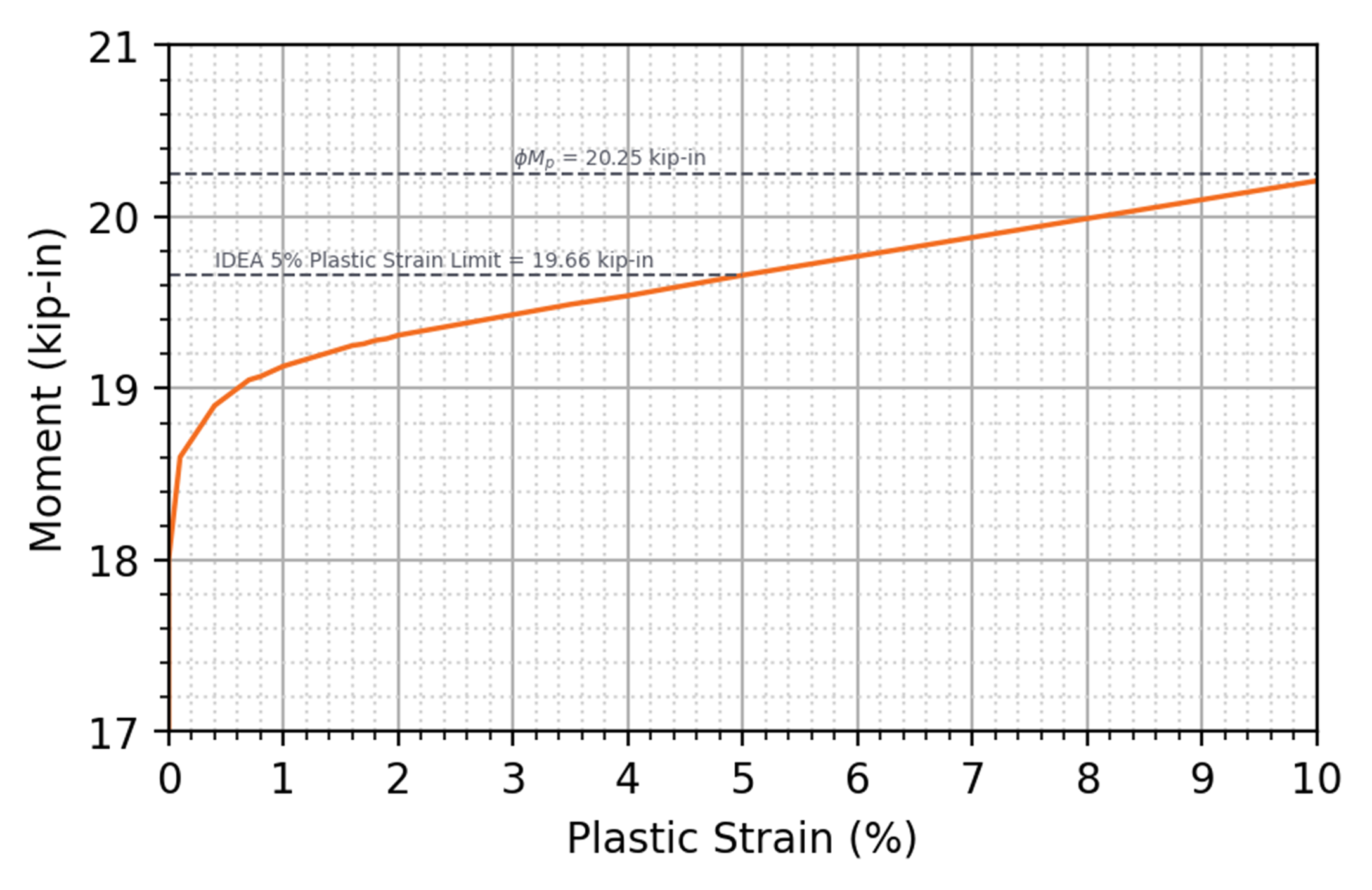
Momento aplicado frente a deformación plástica para una placa cargada en flexión respecto al eje secundario
Rotura a Flexión
La rotura a flexión es uno de los estados límite identificados para los elementos afectados de elementos estructurales y elementos de conexión a flexión en la Sección J4.5 de la Especificación AISC. La rotura a flexión puede producirse cuando se aplica un momento a una sección transversal con material eliminado, como los orificios de los pernos. El Capítulo J de la Especificación AISC no define la resistencia disponible para el estado límite de rotura a flexión. La Sección F13.1 de la Especificación AISC aborda la rotura a flexión para elementos con orificios de pernos en el ala a tracción, y en la Parte 9 del Manual AISC se proporciona orientación para la rotura a flexión de elementos afectados y de conexión. Concretamente, la Ecuación 9-8 del Manual AISC define la resistencia nominal a la rotura por flexión como el producto de la resistencia mínima especificada a tracción y el módulo resistente plástico neto del elemento afectado o de conexión. El Manual AISC define además el factor de resistencia como \(\phi=0.75\) y el coeficiente de seguridad como \(\Omega = 2.00\) para la rotura a flexión.
Al igual que con el estado límite de rotura a tracción, IDEA StatiCa no evalúa las ecuaciones de resistencia para la rotura a flexión. En su lugar, el estado límite de rotura a flexión se evalúa utilizando el límite de deformación plástica. Por lo tanto, al igual que para la rotura a tracción, surgen diferencias porque la relación tensión-deformación utilizada en IDEA StatiCa tiene un endurecimiento por deformación mínimo tras la plastificación, mientras que la ecuación de diseño utiliza la resistencia a tracción del material, y porque IDEA StatiCa reduce la tensión en la plastificación por un factor de 0,9 (para LRFD), mientras que se utiliza un factor de resistencia de 0,75 para la rotura a flexión. Surgen diferencias adicionales, específicas de la rotura a flexión, por el uso del módulo resistente plástico en la ecuación de diseño, que asume una tensión uniforme tanto a tracción como a compresión. En IDEA StatiCa, las tensiones son un resultado del análisis y no necesariamente uniformes.
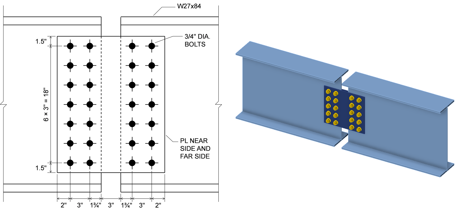
Para examinar el efecto neto de estas diferencias, considérense las placas de empalme ensayadas por Mohr y Murray (2008). Ensayaron 14 especímenes en total; aquí se investigan los seis ensayos de la primera serie con tres patrones de pernos diferentes. Las placas se instalaron entre dos vigas W27x84. El conjunto completo se cargó en flexión en cuatro puntos, sometiendo la placa a flexión pura. Las dimensiones de las placas más grandes, las que tienen 7 pernos en cada fila vertical, se muestran a continuación. También se realizaron ensayos con 5 y 3 pernos en cada fila vertical con dimensiones similares. La resistencia a la fluencia medida de las placas fue Fy = 49,5 ksi, la resistencia a tracción medida de las placas fue Fu = 72,1 ksi, y el espesor medido de las placas fue t = 0,370 pulg.
La resistencia de cálculo, \(\phi M_n\), de las placas se calculó según la Especificación AISC para el estado límite de plastificación a flexión y según el Manual AISC para el estado límite de rotura a flexión. En estos cálculos se utilizaron propiedades materiales y geométricas medidas y se aplicaron factores de resistencia. También se construyeron modelos de IDEA StatiCa de las tres uniones utilizando propiedades materiales y geométricas medidas de las placas. Los factores de resistencia se mantuvieron en sus valores predeterminados. Las propiedades de las vigas y los pernos se incrementaron respecto a los valores nominales para garantizar que el modo de fallo coincidiera con el del experimento. El momento aplicado máximo permitido de IDEA StatiCa, MIDEA, se determinó de forma iterativa. Los resultados de estos cálculos se muestran en la figura siguiente junto con la resistencia experimental, Mexp. La resistencia experimental se tomó como la media de las resistencias reportadas para los dos especímenes de cada patrón de pernos. Los momentos en la figura corresponden a cada placa, teniendo en cuenta que había dos placas por espécimen, una a cada lado de las vigas.
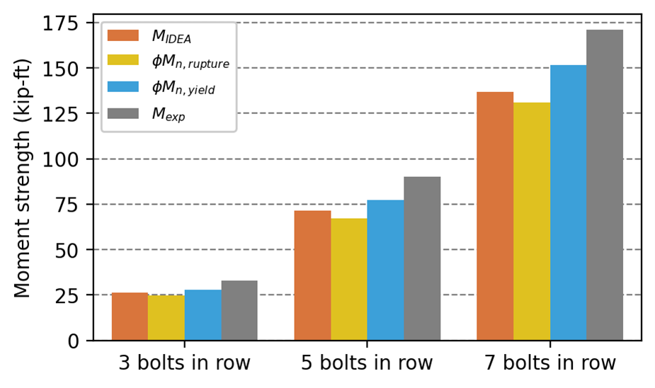
En los experimentos físicos, todos los especímenes fallaron por rotura a flexión. La rotura a flexión también controla la resistencia a momento de las placas, ya que \(\phi M_{n,rupture} < \phi M_{n,yield}\). Sin embargo, IDEA StatiCa no distingue claramente entre estos dos estados límite; ambos se evalúan utilizando el límite de deformación plástica del 5%. La deformación plástica en las placas a la carga aplicada máxima permitida se muestra para los casos con 7 y 3 pernos en cada fila vertical a continuación.
El momento aplicado máximo permitido de IDEA StatiCa, MIDEA, es aproximadamente un 5% mayor que \(\phi M_{n,rupture}\) para estos casos, un resultado ligeramente no conservador en comparación con la ecuación del Manual AISC. Sin embargo, MIDEA es aproximadamente un 20% menor que Mexp para estos casos. Aunque se espera que MIDEA sea menor que Mexp dado que no se aplicó ningún factor de reducción a los resultados experimentales, la diferencia indica que existe un margen de seguridad.
Aplastamiento del Hormigón
En las bases de pilares se desarrollan tensiones de apoyo sobre las zapatas y cimentaciones de hormigón. La Sección J8 de la Especificación AISC (2022) proporciona una ecuación para la resistencia del hormigón para el estado límite de aplastamiento del hormigón, idéntica a las disposiciones equivalentes de ACI 318 (ACI 2019). La resistencia depende del área de acero que apoya sobre un soporte de hormigón, la geometría del soporte de hormigón y la resistencia a compresión especificada del hormigón.
IDEA StatiCa utiliza estas disposiciones para evaluar el aplastamiento del hormigón. Sin embargo, algunas diferencias entre IDEA StatiCa y los cálculos manuales tradicionales en la evaluación del aplastamiento del hormigón surgen debido a diferencias en el enfoque de análisis subyacente. En los cálculos manuales es habitual asumir que la tensión de apoyo es uniforme sobre el área de contacto. En IDEA StatiCa, la rigidez de la zapata de hormigón, la rigidez de la base del pilar y el contacto se modelan explícitamente, resultando en una distribución de tensiones de apoyo más realista físicamente y no uniforme. El área de apoyo en IDEA StatiCa se calcula como el área de acero que está en contacto con el hormigón y con una tensión de apoyo mayor que un valor de corte (el corte de tensión se define como una relación respecto a la tensión de apoyo máxima, con la relación seleccionable en la configuración de código). Esto puede dar lugar a una forma relativamente compleja para el área de apoyo, como se muestra en la figura siguiente. No obstante, la fuerza de apoyo total, el área de apoyo y el área geométricamente similar en el soporte de hormigón se calculan para su uso en la ecuación normativa.
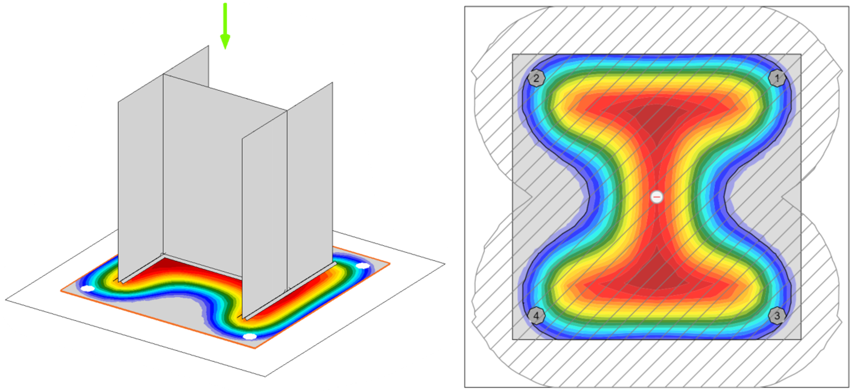
Vista tridimensional (izquierda) y planta (derecha) de la tensión en el hormigón en la interfaz acero-hormigón de una unión de placa base cargada concéntricamente. El límite del área de apoyo (A1 en la Sección J8 de la Especificación AISC) se muestra como una línea negra continua en la planta. Nótese la forma irregular que sigue los contornos de tensión y los orificios de los pernos de anclaje. La superficie de apoyo del hormigón (A2 en la Sección J8 de la Especificación AISC) se muestra como la región rayada de la planta y es igualmente irregular.
Se puede encontrar información adicional en estos artículos:
- https://www.ideastatica.com/support-center/general-theoretical-background#Structural_model_of_a_concrete_block
- https://www.ideastatica.com/support-center/check-of-components-according-to-aisc
- https://www.ideastatica.com/support-center/check-of-concrete-blocks-according-to-aisc
- https://www.ideastatica.com/support-center/base-plate-connections-aisc
Flexión Local del Ala
La flexión local del ala es uno de los estados límite aplicables a las fuerzas concentradas aplicadas perpendicularmente al ala de perfiles de ala ancha y formas similares construidas. Se aplica únicamente a fuerzas concentradas de tracción. La resistencia nominal para el estado límite de flexión local del ala se define en la Sección J10.1 de la Especificación AISC (2022).
Tal como se describe en el comentario a la Sección J10.1, el estado límite de flexión local del ala fue concebido originalmente para prevenir la fractura de la soldadura, que podría producirse prematuramente debido a solicitaciones no uniformes causadas por la deformación del ala. Sin embargo, ensayos más recientes han demostrado que la fractura de la soldadura no se produce cuando se supera la resistencia a la flexión local del ala, sino que la resistencia a la flexión local del ala representa un límite inferior a partir del cual la deformación del ala podría dar lugar a un pandeo local prematuro del ala o ser perjudicial para otros aspectos del comportamiento del elemento. El comentario señala además que, aunque las deformaciones del ala también pueden producirse bajo fuerzas de compresión, la Especificación AISC no requiere que la flexión local del ala se verifique para fuerzas de compresión, ya que es habitual realizar la verificación únicamente para fuerzas de tracción.
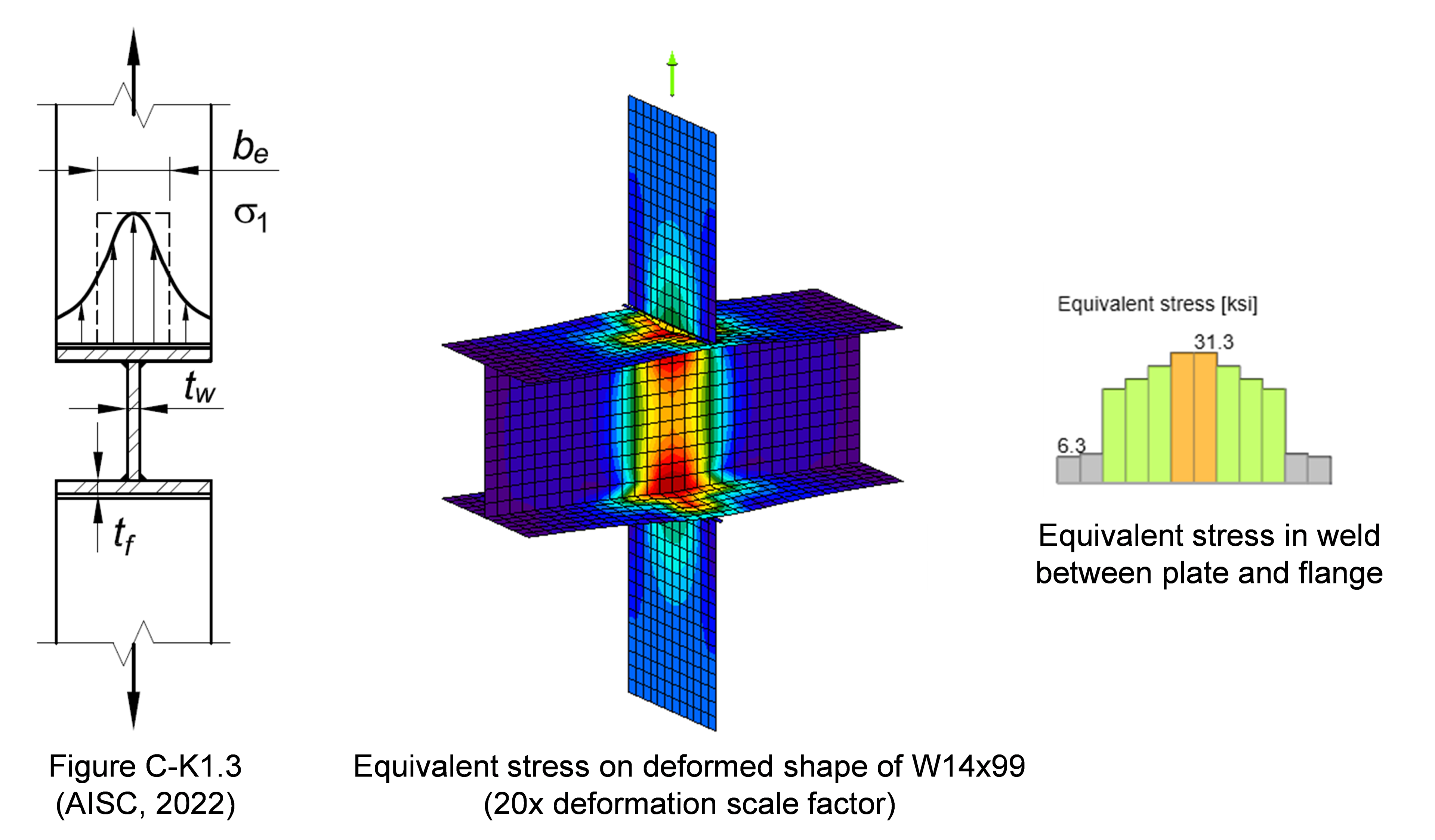
Como se muestra en la figura anterior, tanto la distribución no uniforme de tensiones como las deformaciones del ala se modelan explícitamente en IDEA StatiCa. Cada segmento de soldadura se verifica independientemente en cuanto a resistencia. Los casos como el mostrado en la figura anterior fueron examinados en la calibración y posterior validación y verificación del modelo de soldadura en IDEA StatiCa. Sin embargo, para perfiles distintos de los HSS, las deformaciones locales del ala no se verifican frente a un límite, su efecto sobre el comportamiento del elemento no se evalúa y su magnitud no puede obtenerse directamente del modelo. Como resultado, el estado límite de flexión local del ala no se evalúa en IDEA StatiCa. En los casos en que la flexión local del ala controla los cálculos tradicionales, pueden obtenerse resistencias significativamente mayores con IDEA StatiCa. Cuando las deformaciones del ala son una preocupación, se recomienda evaluar el estado límite fuera de IDEA StatiCa.
Nótese que la plastificación a flexión de las alas en uniones atornilladas se considera un estado límite independiente. En los cálculos tradicionales, la resistencia disponible se determina típicamente utilizando la teoría de líneas de plastificación, tal como describe Dowswell (2011) para uniones generales o Eatherton y Murray (2023) para uniones de momento con placa de testa. IDEA StatiCa contempla este estado límite mediante el modelado explícito del ala, como se muestra en la figura siguiente.
Plastificación Local del Alma
La plastificación local del alma es uno de los estados límite aplicables a las fuerzas concentradas aplicadas perpendicularmente al ala de perfiles de ala ancha y formas similares construidas. Las ecuaciones de resistencia nominal para la plastificación local del alma en la Sección J10.2 de la Especificación AISC se basan en la plastificación del alma a lo largo de una longitud igual a la longitud de apoyo más una difusión asumida de la fuerza a través del ala. Aunque la plastificación del alma se modela explícitamente en IDEA StatiCa, varias características de las ecuaciones de diseño no lo están. Las ecuaciones asumen un gradiente de tensiones de 2,5:1 a través del ala y el acuerdo de los perfiles laminados. En IDEA StatiCa, el ala se modela con elementos de lámina y el acuerdo se desprecia, por lo que la difusión de fuerzas depende en gran medida de las restricciones entre el ala y el alma. Existen dos ecuaciones separadas en la Sección J10.2 de la Especificación AISC para la plastificación local del alma según la distancia de la fuerza respecto a los extremos del elemento. En IDEA StatiCa, la reducción de resistencia debida a la proximidad al extremo del elemento se captura modelando directamente el elemento. Se aplica un factor de resistencia de ϕ = 1,00 y un coeficiente de seguridad de Ω = 1,50 al estado límite de plastificación local del alma. IDEA StatiCa no utiliza estos factores y en su lugar reduce el límite elástico por un factor de 0,9 para LRFD o dividiéndolo por 1,67 para ASD, basándose en el factor de resistencia y el coeficiente de seguridad típicos para la plastificación.
El efecto global de estas diferencias ha sido investigado para uniones de viga sobre pilar en este artículo y para fuerzas concentradas genéricas en este informe.
Pandeo por Compresión del Alma
El pandeo por compresión del alma es uno de los estados límite aplicables a las fuerzas concentradas aplicadas perpendicularmente al ala de perfiles de ala ancha y formas similares construidas. Se aplica cuando un par de fuerzas comprimen el alma desde ambas alas en el mismo punto a lo largo de la longitud del elemento. La Sección J10.5 de la Especificación AISC proporciona una ecuación para la resistencia nominal al pandeo por compresión del alma. La ecuación se basa en la resistencia al pandeo elástico de una placa simplemente apoyada sometida a fuerzas concentradas iguales y opuestas.
En IDEA StatiCa, el diseño frente al pandeo por compresión del alma puede lograrse asegurando que la carga de pandeo crítico elástico sea suficientemente grande (véase la discusión en la entrada sobre Plastificación y Pandeo a Compresión). Mediante comparaciones con análisis geométrico y materialmente no lineal con imperfecciones incluidas (GMNIA), se determinó que una relación de carga de pandeo crítico elástico de 3 es un límite inferior apropiado.
Plastificación a Cortante de la Zona de Panel del Alma
La resistencia disponible para el estado límite de plastificación a cortante de la zona de panel de perfiles de ala ancha y formas similares construidas se define en la Sección J10.6 de la Especificación AISC. En esta sección se proporcionan cuatro ecuaciones diferentes para la resistencia nominal. Se proporciona un par de ecuaciones para cuando el efecto de la deformación inelástica de la zona de panel sobre la estabilidad del pórtico no se tiene en cuenta en el análisis, y otro par para cuando sí se tiene en cuenta. El primer par de ecuaciones limita el comportamiento de la zona de panel al rango elástico. El segundo par de ecuaciones proporciona una mayor resistencia; sin embargo, es necesaria la deformación plástica de la zona de panel para alcanzar una mayor resistencia. Las deformaciones adicionales pueden aumentar significativamente las deformaciones globales del pórtico y los efectos de segundo orden. Si la posibilidad de deformación inelástica de la zona de panel no se tiene en cuenta en el cálculo de las resistencias requeridas de los elementos y las uniones, la Sección J10.6 de la Especificación AISC requiere que el comportamiento de la zona de panel se limite al rango elástico.
En IDEA StatiCa, la plastificación a cortante de la zona de panel se modela explícitamente con elementos de lámina no lineales y se limita mediante un límite de deformación plástica. El estado límite de plastificación a cortante de la zona de panel fue explorado para uniones de momento con placa de testa extendida en este artículo y para uniones de momento con placa de ala atornillada en este artículo. Utilizando el límite de deformación plástica predeterminado del 5%, la resistencia de IDEA StatiCa supera la de la Especificación AISC para cuando el efecto de la deformación inelástica de la zona de panel sobre la estabilidad del pórtico no se tiene en cuenta en el análisis. Sin embargo, reducir el límite de deformación plástica a un valor pequeño (p. ej., 0,1%) en IDEA StatiCa impone un comportamiento esencialmente elástico y da lugar a resistencias precisas en comparación con las ecuaciones de la Especificación AISC para cuando el efecto de la deformación inelástica de la zona de panel sobre la estabilidad del pórtico no se tiene en cuenta en el análisis.
Los ingenieros deben saber si el efecto de la deformación inelástica de la zona de panel sobre la estabilidad del pórtico se tuvo en cuenta en el análisis para determinar las resistencias requeridas (es decir, no el análisis de IDEA StatiCa). Y, si no fue así, deben limitar el comportamiento de la zona de panel a un comportamiento esencialmente elástico.
Uniones a Elementos HSS
El Capítulo K de la Especificación AISC (2022) incluye requisitos adicionales, más allá de los del Capítulo J, aplicables a las uniones con elementos HSS y secciones en cajón que se comportan como elementos HSS. El Capítulo K está organizado por tipo de unión y los requisitos van frecuentemente acompañados de límites de aplicabilidad. Sin embargo, el Capítulo K no prohíbe el uso de uniones de otras configuraciones o las que están fuera de los límites de aplicabilidad.
Los estados límite descritos en las tablas del Capítulo K se evalúan en IDEA StatiCa mediante modelado explícito y el límite de deformación plástica del 5%. Los efectos de los parámetros definidos en la Sección K1, incluyendo el ancho efectivo para uniones a HSS rectangulares para tener en cuenta las distribuciones de tensiones no uniformes, el parámetro de interacción de tensión en el cordón y la distancia al extremo, también se modelan explícitamente. Para aumentar la precisión, la no linealidad geométrica se incluye en el modelo por defecto cuando se utiliza una sección transversal hueca como elemento de apoyo.
El comentario al Capítulo K indica: "Cuando se utiliza el análisis de elementos finitos inelástico, las deformaciones máximas en los elementos de lámina gruesa (T × T × T) no deben superar 0,02/T a la capacidad nominal, donde T es el espesor en pulgadas." Despreciando la diferencia entre deformación y deformación plástica, el valor límite de esta recomendación es mayor que el 5% utilizado por IDEA StatiCa cuando el espesor es inferior a 0,4 pulg. Aunque el límite de deformación de la recomendación del comentario es más restrictivo que el límite predeterminado en IDEA StatiCa para tubos más gruesos, el límite de deformación plástica del 5% está más ampliamente reconocido como un límite aceptable para el diseño en resistencia, incluyendo por el Steel Tube Institute.
El Capítulo K se basa únicamente en estados límite de resistencia. Como resultado, pueden producirse grandes deformaciones en uniones que cumplen los requisitos del Capítulo K. No obstante, la deformación local fuera del plano de los elementos HSS se verifica en IDEA StatiCa frente a un límite del 3% de la menor dimensión transversal de la sección transversal (es decir, diámetro o anchura), basándose en los requisitos de otras normas.
Dado que las disposiciones del Capítulo K se basan en gran medida en investigaciones internacionales y en el trabajo de comités internacionales, las verificaciones con otras normas son generalmente informativas para la práctica estadounidense. En el sitio web de IDEA StatiCa están disponibles varios estudios de verificación para uniones a elementos HSS, incluyendo uniones entre secciones huecas rectangulares, secciones huecas circulares, placas y secciones huecas rectangulares, y placas y secciones huecas circulares.
Consideraciones y Requisitos de Diseño
Base de Diseño
El diseño por resistencia según la Especificación AISC se realiza con las disposiciones para el diseño por factor de carga y resistencia (LRFD) o con las disposiciones para el diseño por resistencia admisible (ASD). Aunque estos dos enfoques tienen diferentes resistencias requeridas y diferentes resistencias disponibles, las resistencias nominales son las mismas y los diseños finales deberían ser similares, si no idénticos.
| Criterio de resistencia | Resistencia requerida | Resistencia disponible | Resistencia nominal | |
| LRFD | \(R_u \le \phi R_n\) | Ru calculada usando combinaciones de carga LRFD (p. ej., 1.2D + 1.6L + 0.5Lr) | \(\phi\)Rn también denominada resistencia de cálculo (\(\phi\) es un factor de resistencia) | Rn |
| ASD | \(R_a \le R_n/\Omega\) | Ra calculada usando combinaciones de carga ASD (p. ej., D + L) | Rn/Ω también denominada resistencia admisible (Ω es un factor de seguridad) | Rn |
Las resistencias requeridas son mayores para LRFD que para ASD debido a los mayores factores de carga en las combinaciones de carga LRFD. También pueden surgir diferencias en las resistencias requeridas cuando estas se calculan mediante análisis no lineal y el nivel de no linealidad depende del nivel de carga. Para compensar esto en el diseño por estabilidad, la Especificación AISC requiere que todos los efectos dependientes de la carga se calculen a un nivel de carga correspondiente a las combinaciones de carga LRFD o 1.6 veces las combinaciones de carga ASD. IDEA StatiCa sigue un enfoque diferente. En IDEA StatiCa, el límite elástico para los elementos de lámina se toma como 0.9Fy para LRFD y Fy/1.67 para ASD, donde 0.9 y 1.67 corresponden al factor de resistencia y al factor de seguridad típicos para los estados límite de plastificación. En la mayoría de los casos, esto resulta en cargas aplicadas máximas permitidas que son 1.5 veces mayores para LRFD que para ASD, de acuerdo con las disposiciones de la Especificación AISC. Sin embargo, el módulo de elasticidad no se reduce en IDEA StatiCa ni para LRFD ni para ASD. Por lo tanto, la relación entre rigidez y resistencia difiere entre enfoques, lo que genera algunas consecuencias en el diseño. Para el pandeo, la relación límite de carga de pandeo elástico difiere entre LRFD y ASD. Además, cuando la rigidez de una unión afecta a su resistencia, p. ej., en uniones soldadas largas, la relación de carga aplicada máxima permitida entre LRFD y ASD puede desviarse de 1.5. La mayoría de los estudios de validación que comparan IDEA StatiCa con la Especificación AISC se realizaron para LRFD.
IDEA StatiCa implementa las disposiciones para ASD definidas en la Especificación AISC 2022. Las disposiciones de la Especificación AISC 2022 para ASD difieren de las de normas históricas como la Especificación AISC de 1989, incluida en el Manual AISC de la 9ª edición (comúnmente conocido como el "libro verde"). Las disposiciones históricas para ASD se centraban en el comportamiento elástico y presentaban más diferencias con LRFD. Las disposiciones actuales para ASD son más coherentes con LRFD, incluidos los cálculos comunes de resistencia nominal.
Materiales de Acero Estructural
La Sección A3.1 de la Especificación AISC incluye requisitos para los materiales de acero estructural. En esta sección, la Tabla A3.1 enumera materiales específicos que tienen un historial de rendimiento satisfactorio y se considera que funcionan según lo previsto en las disposiciones de la Especificación AISC. Los materiales enumerados incluyen los de perfiles laminados con límite elástico de hasta 80 ksi y chapas con límite elástico de hasta 100 ksi. Se permiten materiales distintos a los enumerados en la Tabla A3.1 cuando el ingeniero de registro determina que su uso es aceptable. Muchos factores pueden afectar la idoneidad de los materiales, incluidos el uso previsto, las propiedades de resistencia en direcciones transversales, la ductilidad y la soldabilidad.
Dada la amplia verificación de IDEA StatiCa con respecto a las disposiciones de la Especificación AISC, los materiales enumerados en la Tabla A3.1 también pueden considerarse que funcionan según lo previsto en el software. El uso de materiales no enumerados en la Tabla A3.1 no está prohibido, pero queda sujeto al criterio del ingeniero de registro. El comentario sobre la Sección A3.1 de la Especificación AISC incluye una discusión sobre los factores que afectan la idoneidad de los materiales y orientación para evaluar dicha idoneidad.
Fuerza de palanca
En las uniones atornilladas, el contacto entre los elementos de unión puede aumentar las fuerzas de tracción más allá de las debidas únicamente a las cargas aplicadas. Este fenómeno se conoce como fuerza de palanca y solo ocurre en uniones con fuerzas de tracción en los tornillos. El contacto que incrementa las fuerzas en los tornillos se produce debido a la deformación del elemento de unión. Por lo tanto, la fuerza de palanca es una consideración de diseño tanto para los tornillos como para los elementos de unión.
La rigidez y resistencia relativas de los tornillos y los elementos de unión controlan el comportamiento. Si los elementos de unión son rígidos en relación con los tornillos, entonces los elementos de unión se deformarán sin doblarse hacia atrás y hacer contacto, y no se producirá fuerza de palanca. En este caso, la resistencia de los tornillos controlará el diseño. Si los elementos de unión son débiles en relación con los tornillos, entonces los elementos de unión cederán e impartirán fuerzas de palanca sobre los tornillos, pero también limitando la fuerza en los tornillos. En este caso, la resistencia de los elementos de unión controlará el diseño. En un punto intermedio, la resistencia de los tornillos y los elementos de unión controlan simultáneamente el diseño.
La guía para considerar la fuerza de palanca en el diseño se proporciona en la Parte 9 del Manual AISC. Las ecuaciones presentadas en el Manual AISC fueron desarrolladas para los casos comunes de una sección en T y angulares espalda con espalda, y validadas con datos experimentales. IDEA StatiCa modela explícitamente la rigidez y resistencia de los tornillos y los elementos de unión, incluyendo el contacto, por lo que la fuerza de palanca es capturada de forma natural por el análisis independientemente de la configuración específica. Se ha realizado una comparación entre las ecuaciones del Manual AISC y los resultados de IDEA StatiCa para uniones de perfil en T. También se ha realizado una comparación similar con el enfoque de diseño para la fuerza de palanca recomendado en la Guide to Design Criteria for Bolted and Riveted Joints (Kulak et al. 1987). La fuerza de palanca aparece en otros ejemplos de verificación, incluyendo uniones de arriostramiento y uniones de momento con placa de testa extendida.
Compatibilidad de Deformaciones en Uniones Largas
En uniones largas cargadas en los extremos, la diferencia de alargamiento entre los elementos conectados es mayor en los extremos de la unión. Como resultado, la tensión en los tornillos y soldaduras en uniones largas cargadas en los extremos no es uniforme. Dado que es habitual en los cálculos tradicionales asumir una tensión uniforme, la Especificación AISC incluye reducciones a la longitud de las soldaduras largas cargadas en los extremos y a la tensión cortante nominal de los tornillos. La Sección J2.2b de la Especificación AISC define la longitud efectiva de las soldaduras en ángulo cargadas en los extremos, incluyendo reducciones cuando la longitud de la soldadura supera 100 veces el tamaño de la soldadura. Los valores de tensión cortante nominal en la Tabla J3.2 de la Especificación AISC incluyen una reducción del 10% para tener en cuenta los efectos de longitud, y se requiere una reducción adicional para uniones cargadas en los extremos con una longitud del patrón de elementos de fijación superior a 38 in.
IDEA StatiCa no implementa estas reducciones directamente. En cambio, el comportamiento subyacente que motiva estas reducciones se modela explícitamente. IDEA StatiCa modela la rigidez de los tornillos, soldaduras y elementos de conexión, por lo que la distribución no uniforme de tensiones en tornillos y soldaduras surge de forma natural. Al evaluar individualmente la resistencia de los tornillos y los segmentos de soldadura, la resistencia de la unión resultante es comparable a la obtenida mediante cálculos tradicionales. En este artículo se presenta una comparación detallada entre IDEA StatiCa y los resultados obtenidos mediante cálculos tradicionales para uniones largas cargadas en los extremos.
Compatibilidad de Deformaciones en Grupos de Pernos y Soldaduras con Carga Excéntrica
Los pernos y soldaduras en grupos con carga excéntrica están sujetos a cortante directo más cortante adicional por el momento inducido. La tensión resultante en los pernos o soldaduras varía tanto en magnitud como en dirección de perno a perno y de segmento de soldadura a segmento de soldadura. Tal como se describe en las Partes 7 y 8 del Manual AISC, los ingenieros pueden utilizar el método del centro instantáneo de rotación o el método elástico para analizar grupos de pernos o soldaduras con carga excéntrica. Los cálculos mediante el método del centro instantáneo de rotación se realizan normalmente utilizando valores tabulados proporcionados en el Manual AISC.
En IDEA StatiCa, la resistencia requerida de los pernos y segmentos de soldadura se determina a partir de los resultados del análisis no lineal. Cada perno y segmento de soldadura se modela individualmente y se impone el equilibrio. Las resistencias disponibles se determinan de acuerdo con la Especificación AISC.
El método del centro instantáneo de rotación también se basa en un análisis no lineal, pero existen diferencias clave entre los análisis no lineales del método del centro instantáneo de rotación e IDEA StatiCa. En el método del centro instantáneo de rotación, se asume que los elementos de unión son rígidos, lo cual no es el caso en IDEA StatiCa. La respuesta fuerza-deformación de los pernos y soldaduras también difiere entre los dos métodos. La respuesta fuerza-deformación utilizada en IDEA StatiCa para pernos y soldaduras es bilineal y se describe en los fundamentos teóricos.
Las diferencias generalmente resultan en resistencias similares o inferiores en IDEA StatiCa, como se muestra en este artículo sobre uniones de placa de ménsula. También se realizan comparaciones entre los cálculos tradicionales e IDEA StatiCa para grupos de pernos con carga excéntrica en este artículo sobre uniones de cortante de placa simple.
Pernos en Combinación con Soldaduras
La predicción precisa de la resistencia es más difícil cuando los pernos y las soldaduras comparten carga en una superficie de contacto común. La menor ductilidad de las soldaduras en comparación con los pernos puede dar lugar a una fractura frágil antes de que se alcance la resistencia total del perno. La Sección J1.8 de la Especificación AISC permite considerar que los pernos y las soldaduras comparten carga solo en determinadas circunstancias.
Según la Sección J1.8, los pernos pueden considerarse como compartiendo carga con las soldaduras únicamente en el diseño de uniones a cortante en una superficie de contacto común donde se considera la compatibilidad de deformaciones entre los pernos y las soldaduras. La sección también describe un caso con pernos de alta resistencia pretensados y soldaduras en ángulo longitudinales, donde se permite determinar la resistencia nominal como la resistencia nominal al deslizamiento más la resistencia nominal de la soldadura. Los pernos y las soldaduras deben soportar cada uno una proporción especificada de la carga, y se aplica un factor de resistencia de ϕ = 0,75 o un coeficiente de seguridad de Ω = 2,00 a la unión combinada.
Las verificaciones de resistencia de pernos y soldaduras son independientes en IDEA StatiCa, sin ningún tratamiento especial para cuando los pernos y las soldaduras comparten carga. Dado el modelado explícito de la rigidez de los pernos, las soldaduras, los elementos estructurales y los elementos de conexión, la compatibilidad de deformaciones siempre se considera en IDEA StatiCa. Cuando los pernos y las soldaduras comparten carga, la resistencia requerida de cada uno se basa en su rigidez relativa y la resistencia disponible se calcula de la manera habitual. Esto es válido incluso para uniones a tracción; por lo tanto, se recomienda no modelar pernos y soldaduras como compartiendo carga para uniones a tracción y en su lugar confiar únicamente en uno u otro.
Para ilustrar las diferencias entre el método proporcionado en la Sección J1.8 de la Especificación AISC e IDEA StatiCa, considérese la unión entre placas sometidas a tracción mostrada a continuación.
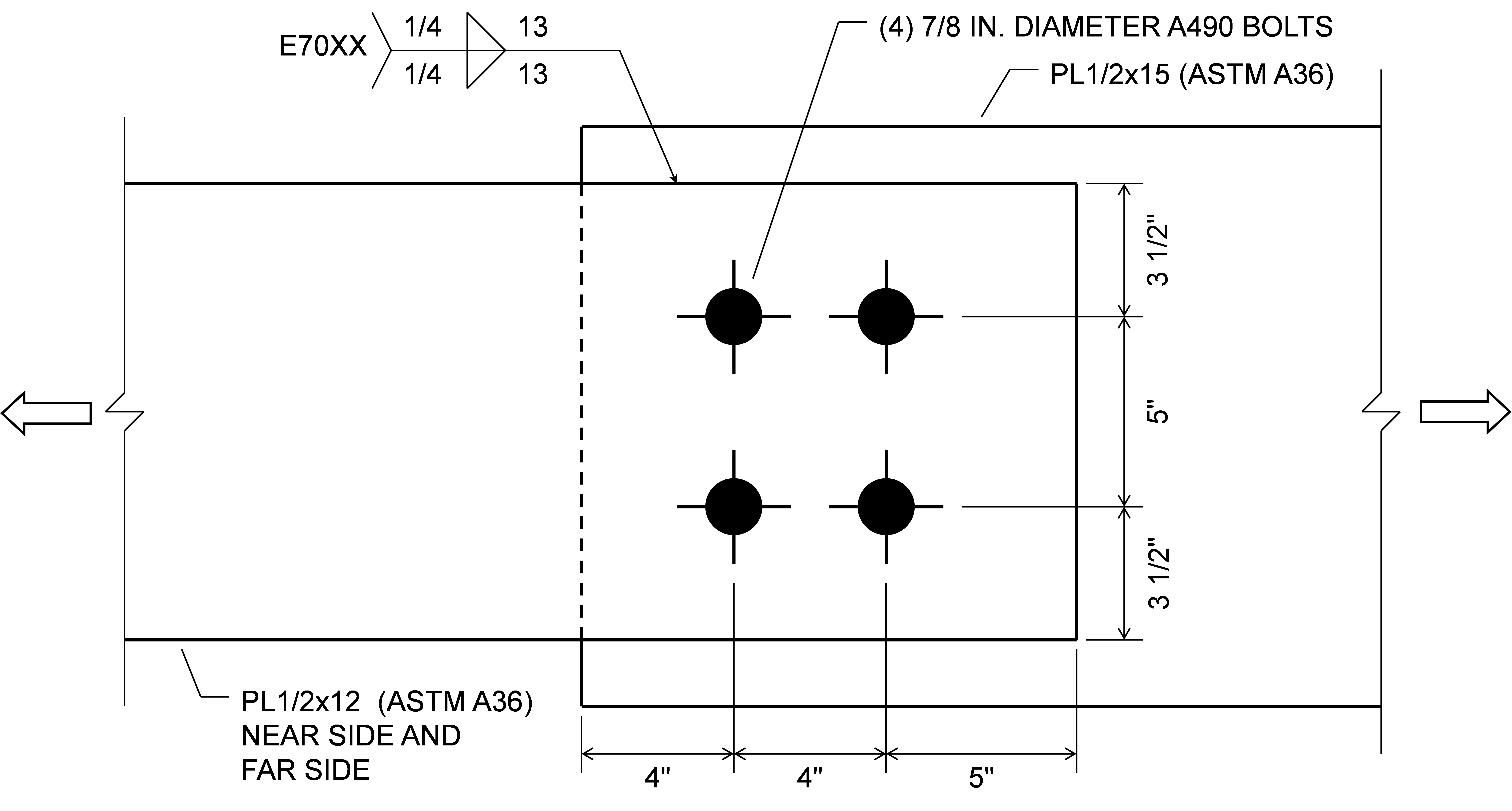
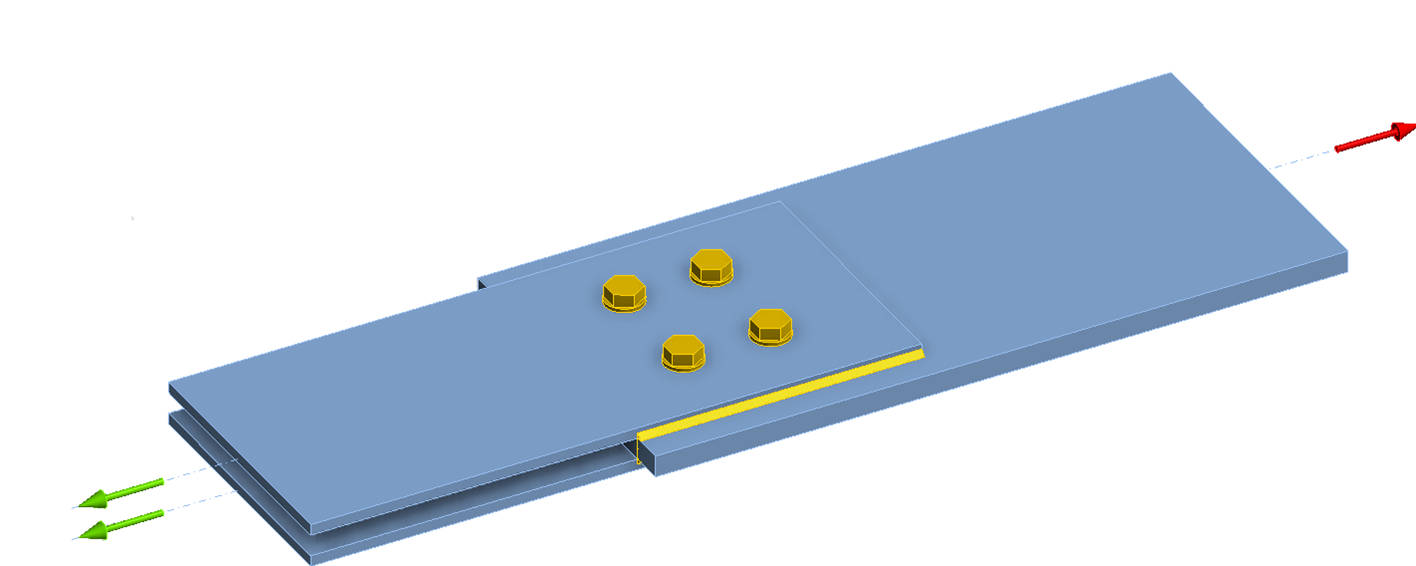
Según la Especificación AISC, cuando la unión se diseña como resistente al deslizamiento, la resistencia de cálculo de los pernos solos es ϕRn = 133 kips (Rn = 133 kips). La resistencia de cálculo de las soldaduras solas es ϕRn = 290 kips (Rn = 386 kips). Al combinar pernos y soldaduras, la resistencia total de la unión es ϕRn = 0,75 (133 + 386) = 389 kips, ya que se cumplen todos los requisitos de la Sección J1.8 para permitir la suma de las resistencias de pernos y soldaduras.
En IDEA StatiCa, la tracción aplicada máxima permitida es de 126 kips cuando solo se modelan los pernos y de 277 kips cuando solo se modelan las soldaduras. La diferencia entre la resistencia de los pernos en IDEA StatiCa y la resistencia de cálculo de 133 kips se debe a que la tracción en los pernos se desarrolla en el modelo y se trata de forma conservadora como una tracción aplicada en IDEA StatiCa (véase la entrada sobre Deslizamiento). La diferencia entre la resistencia de la soldadura en IDEA StatiCa y la resistencia de cálculo de 277 kips se debe a las solicitaciones no uniformes a lo largo de la longitud de la soldadura en IDEA StatiCa. Cuando se modelan tanto los pernos como las soldaduras, la tracción aplicada máxima permitida es de 394 kips, con tanto los pernos como las soldaduras mostrando una utilización del 100%. Este valor es muy comparable a la resistencia de 389 kips de la Especificación AISC.
Si se asume que los pernos son de tipo aplastamiento, la resistencia de cálculo de los pernos según la Especificación AISC es ϕRn = 245 kips. Aunque la Especificación AISC permite considerar que los pernos comparten carga con las soldaduras en uniones a cortante, no proporciona un método para evaluar la resistencia cuando los pernos no cumplen los requisitos de una unión resistente al deslizamiento. Por lo tanto, sería habitual evaluar la resistencia de esta unión como la de las soldaduras solas, es decir, ϕRn = 290 kips.
En IDEA StatiCa, cuando los pernos se modelan como pernos de aplastamiento y las soldaduras no se modelan, la tracción aplicada máxima permitida coincide con la resistencia de cálculo de 245 kips de la Especificación AISC. Cuando los pernos se modelan como pernos de aplastamiento y las soldaduras se modelan, la tracción aplicada máxima permitida es de 311 kips, siendo la resistencia de la soldadura el límite condicionante. Esta resistencia es solo un 12% mayor que la resistencia de las soldaduras solas según IDEA StatiCa. El pequeño incremento de resistencia con la adición de pernos de aplastamiento se debe a que los pernos son menos rígidos que las soldaduras y, por lo tanto, no atraen mucha carga antes de que las soldaduras alcancen el 100% de utilización.
Efecto del Tamaño del Agujero
La Sección J3.3 de la Especificación AISC (2022) describe el uso de agujeros estándar, sobredimensionados, ranurados cortos y ranurados largos para pernos en uniones de acero estructural. Los agujeros estándar son los predeterminados en IDEA StatiCa. Los agujeros sobredimensionados se pueden obtener editando el diámetro del agujero en el conjunto de pernos. Los agujeros ranurados se pueden definir para placas en el editor de placas.
El tamaño del agujero afecta a varios aspectos del comportamiento, y algunos requisitos de diseño se basan en el tamaño del agujero.
- El material eliminado para los agujeros de los pernos afecta al área neta. Este efecto se aborda explícitamente en IDEA StatiCa mediante la definición del modelo de elementos de lámina para elementos y elementos de conexión. Sin embargo, las 1/16 in. adicionales por daño requeridas por la Sección B4.3b de la Especificación AISC no se implementan automáticamente (véase Determinación del Área Neta)
- El tamaño del agujero afecta a la distancia libre utilizada para determinar la resistencia al desgarro. Este efecto se aborda explícitamente en IDEA StatiCa calculando la distancia libre en función de la geometría del material conectado y la dirección de la fuerza en el perno individual.
- Los agujeros sobredimensionados no están permitidos en uniones de tipo aplastamiento. IDEA StatiCa no verifica este requisito y permitirá el uso de la transferencia de fuerza cortante por aplastamiento con agujeros sobredimensionados.
- El factor de resistencia para el estado límite de deslizamiento depende del tipo de agujero. IDEA StatiCa no ajusta automáticamente el factor de resistencia según el tipo de agujero. El factor de resistencia se puede establecer manualmente en la Configuración de código.
El tamaño del agujero puede afectar a la respuesta carga-deformación del perno. El modelo carga-deformación del perno utilizado en IDEA StatiCa no depende del tamaño del agujero, pero se asume que la transferencia de cortante es nula en la dirección longitudinal de los agujeros ranurados.
Déficit de Laminación
La variación en la longitud del elemento puede dar lugar a diferencias significativas en las dimensiones utilizadas en el diseño de la unión. En varios cálculos de los Ejemplos de Diseño AISC, se resta una tolerancia de 1/4 de pulgada a una longitud para tener en cuenta el posible déficit de laminación. IDEA StatiCa no tiene en cuenta automáticamente el posible déficit de laminación, pero este puede considerarse definiendo manualmente la unión con el déficit supuesto.
Contacto y Fricción
El acero no puede físicamente atravesar el acero, sin embargo, este es el comportamiento predeterminado en los análisis de elementos finitos. Las superficies de contacto deben definirse para evitar que el material se superponga cuando se deforma. El contacto superficie a superficie se define automáticamente con las operaciones de grupo de tornillos. El contacto superficie a superficie puede definirse con la operación "Grupo de tornillos/contacto". El contacto borde a borde o borde a superficie puede definirse con la operación "Soldadura general o contacto".
No todas las superficies de contacto potenciales se definen automáticamente por IDEA StatiCa. Por lo tanto, es importante que el usuario tenga un buen entendimiento del comportamiento previsto de la unión y examine la forma deformada para confirmar que la unión está modelada y se comporta según lo previsto.
El apoyo por contacto puede ser un medio eficiente de transferencia de fuerzas en una unión si la unión ha sido detallada y las superficies están cuidadosamente preparadas de modo que exista apoyo (Muir 2015). Dado que se requiere un detallado especial para garantizar que el apoyo por contacto sea efectivo, el contacto borde a borde y borde a superficie no se define automáticamente en IDEA StatiCa, pero puede definirse manualmente mediante la operación "Soldadura general o contacto". Las empalmes de columnas atornillados son un ejemplo donde la definición del contacto borde a borde entre los elementos reducirá las demandas en los tornillos, resultando en una unión más eficiente. El uso del apoyo por contacto también puede ser eficiente en combinación con soldaduras entre columnas y placas base. Las soldaduras, por defecto, no se definen con contacto y, por lo tanto, también se verifican para fuerzas de compresión. Combinar operaciones de soldadura y contacto puede permitir el uso de soldaduras más pequeñas. Las soldaduras son rígidas y atraerán carga incluso cuando se combinan con contacto, pero las demandas de fuerzas de compresión rara vez superarán la capacidad, incluso si se reduce el tamaño de la soldadura.
La fricción en las superficies de contacto acero-acero se desprecia de forma conservadora en IDEA StatiCa, excepto para los tornillos designados para transferir fuerzas cortantes mediante fricción (es decir, tornillos de deslizamiento crítico). Considerar la fricción únicamente cuando los tornillos pretensados proporcionan la fuerza de apriete es también habitual en los cálculos tradicionales. Sin embargo, pueden producirse algunas diferencias en los resultados entre IDEA StatiCa y los cálculos tradicionales debido a la fricción. Por ejemplo, la Sección J3.10 de la Especificación AISC define un factor de reducción que se aplica a la resistencia al deslizamiento cuando una unión de deslizamiento crítico está sujeta a tracción y cortante combinados. El factor de reducción se basa en la carga de tracción aplicada a la unión. IDEA StatiCa no tiene forma de cuantificar qué parte de la carga de tracción en un tornillo se debe a la carga aplicada frente a otras fuentes como la fuerza de palanca. Si la fuerza de palanca induce tracción en un tornillo de deslizamiento crítico, entonces la resistencia al deslizamiento se reducirá en IDEA StatiCa. La resistencia al deslizamiento según los cálculos tradicionales no se reduciría. Una investigación detallada de esta diferencia se describe para las uniones en T en este artículo.
Determinación del Área Neta
La Sección B4.3b de la Especificación AISC (2022) requiere que el ancho del agujero de un perno se tome como 1/16 pulg. mayor que la dimensión nominal del agujero al calcular el área neta en tracción o cortante. La implementación de este requisito reduce el área neta para tener en cuenta el posible daño alrededor del agujero de un perno durante las operaciones de taladrado o punzonado. Este requisito afecta a estados límite como la rotura por tracción de la sección neta y la rotura por cortante en bloque, pero no afecta al estado límite de desgarro en los agujeros de los pernos.
En IDEA StatiCa, los conjuntos de pernos predeterminados tienen un diámetro de agujero igual a la dimensión nominal del agujero. Por lo tanto, aunque la 1/16 pulg. puede añadirse manualmente al diámetro del agujero del perno editando el conjunto de pernos, este requisito no se aborda automáticamente en IDEA StatiCa. Si se aumenta el diámetro del agujero del conjunto de pernos, el diámetro aumentado se aplicará a todos los aspectos del análisis, incluida la evaluación del desgarro. En la entrada sobre el Efecto del Tamaño del Agujero se puede encontrar información adicional sobre cómo el tamaño del agujero afecta a los resultados en IDEA StatiCa.
La Sección B4.3b de la Especificación AISC (2022) también incluye disposiciones para la determinación del área neta cuando una cadena de agujeros de pernos se extiende a través de una pieza en cualquier línea diagonal o en zigzag. Para estos casos, el ancho neto de la pieza se obtiene deduciendo del ancho bruto la suma de los diámetros (incluida la 1/16 pulg. por daño) de todos los agujeros de la cadena, y añadiendo, para cada espacio de retícula en la cadena, la cantidad s2/4g, donde
g = separación transversal centro a centro (retícula) entre las líneas de retícula de los elementos de fijación
s = separación longitudinal centro a centro (paso) de dos agujeros de pernos consecutivos cualesquiera
El ancho neto resultante es diferente de la longitud de la superficie de fallo (es decir, la línea roja discontinua en la figura siguiente) y tiene en cuenta la combinación de tracción y cortante a lo largo del plano inclinado. Dado que IDEA StatiCa no calcula explícitamente el área neta, las disposiciones sobre el ancho neto no están implementadas en el software. Sin embargo, la posibilidad de fallo a lo largo de una línea diagonal o en zigzag de pernos, incluida la interacción de tracción y cortante a lo largo del plano inclinado, se captura explícitamente mediante el modelado de los elementos conectados.
El efecto del escalonamiento de las líneas de pernos puede observarse en una unión de empalme simple. Una placa de ensayo se atornilla entre dos placas de reacción y se carga a tracción. El espesor de la placa de ensayo es de 1/2 pulg. y el espesor de cada placa de reacción es de 3/8 pulg. Todas las placas tienen 6 pulg. de ancho y cumplen con ASTM A572 Gr 50 (Fy = 50 ksi, Fu = 65 ksi). La unión tiene (6) pernos A325 de 7/8 pulg. de diámetro en dos líneas escalonadas. La separación entre pernos en una línea es de 3 pulg., la retícula, g, es de 3 pulg., y la distancia al borde es de 1,5 pulg. La cantidad de escalonamiento entre las dos líneas de pernos se mide por la dimensión s.
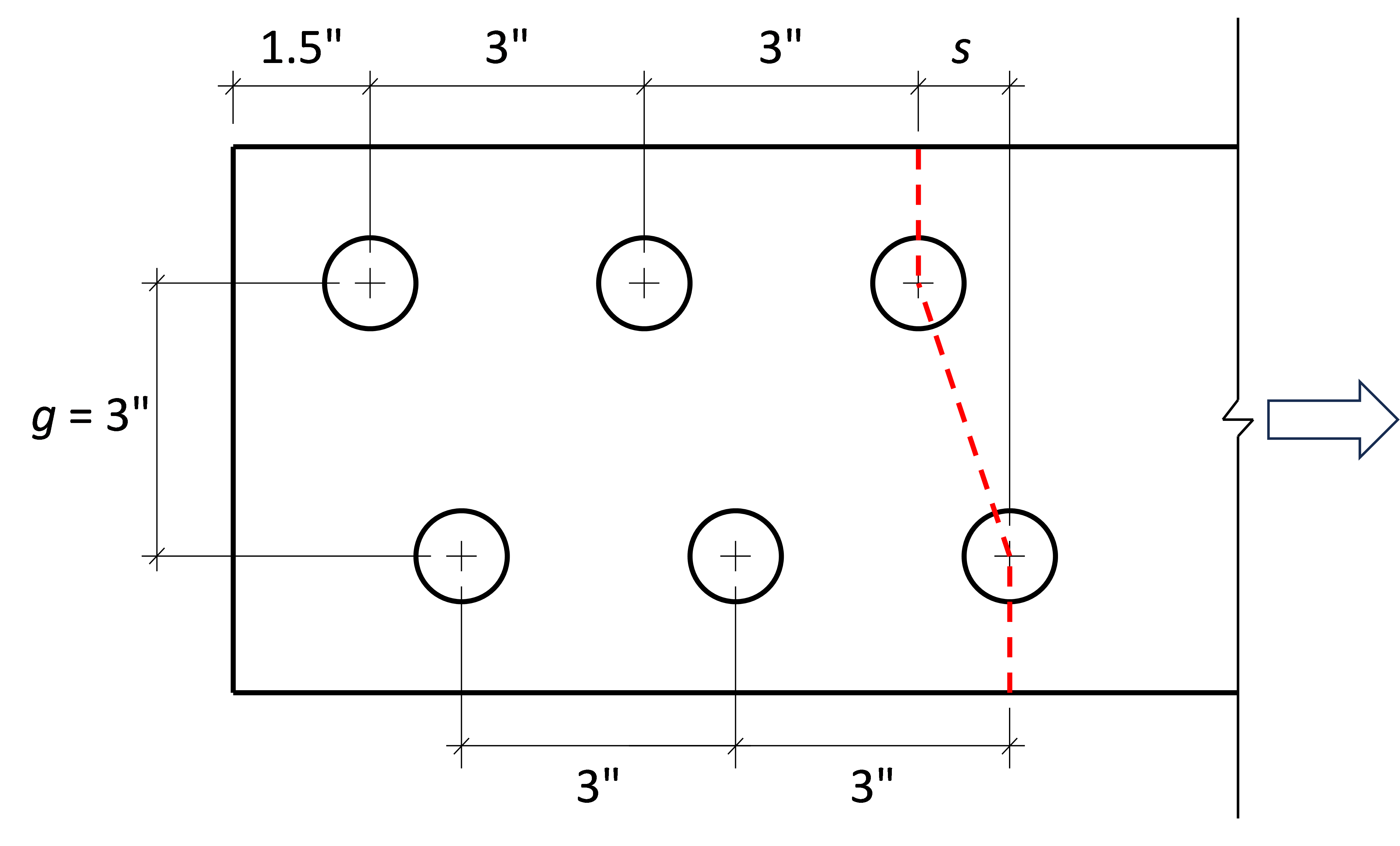
En la figura siguiente se muestra una vista tridimensional de la unión con s = 1,5 pulg.
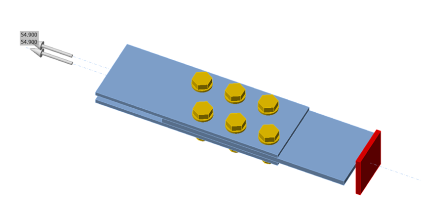
Se realizaron análisis para uniones con la dimensión s variando desde cero (es decir, sin escalonamiento) hasta 3 pulg. en incrementos de 0,5 pulg. La resistencia según la Especificación AISC se calculó utilizando las disposiciones de la Sección B4.3b. El estado límite de rotura por tracción a lo largo de la línea en zigzag mostrada como línea roja discontinua en la figura anterior fue determinante para todos los casos. La resistencia según IDEA StatiCa se determinó de forma iterativa mediante análisis tensión-deformación ajustando la carga aplicada introducida a un valor que el programa considera seguro, pero que si se incrementa en una pequeña cantidad (0,1 kip) el programa consideraría inseguro. El límite de deformación plástica del 5% fue determinante para todos los casos. Los resultados de los análisis se muestran en la figura siguiente.
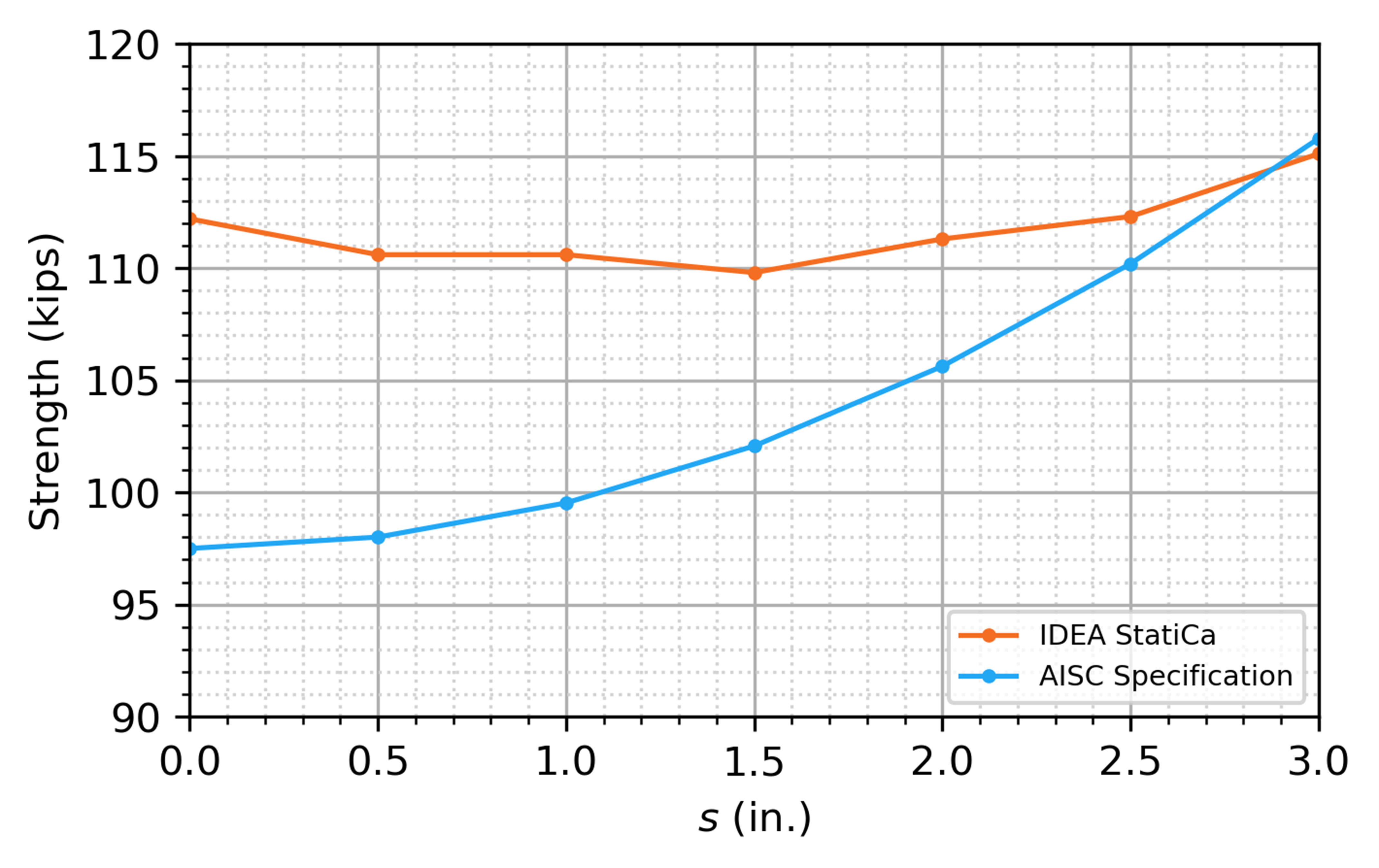
Los resultados de la Especificación AISC muestran una clara tendencia de aumento de la resistencia con la dimensión s. Los resultados de IDEA StatiCa muestran menor sensibilidad a la dimensión s y la resistencia es mayor que la obtenida con la Especificación AISC para todos los casos excepto el de s = 3 pulg. Sin embargo, el patrón de fallo en zigzag esperado queda capturado por el modelo, como se demuestra en la figura siguiente, que muestra la deformación plástica en la placa de ensayo bajo la carga aplicada máxima permitida.
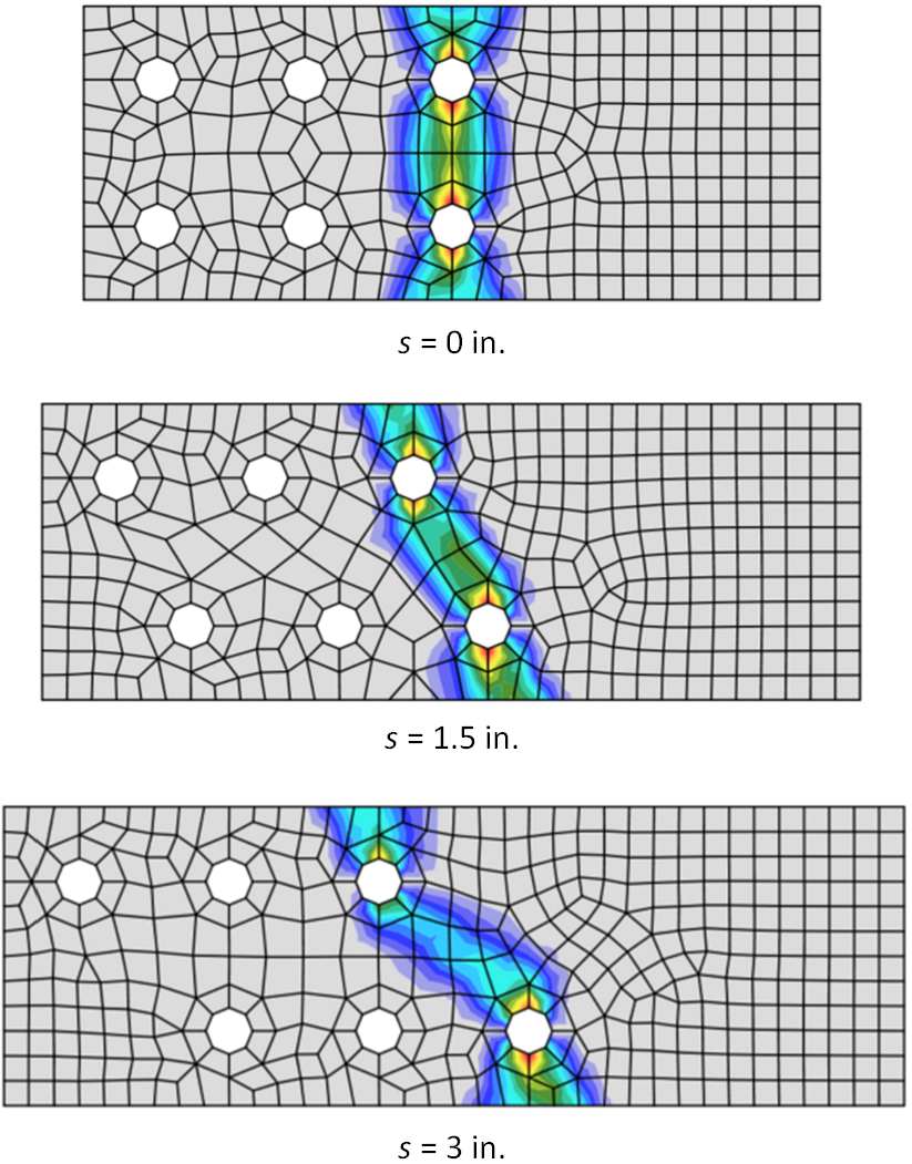
Requisitos de Tamaño de Soldadura en Ángulo
La Sección J2.2b de la Especificación AISC (2022) incluye limitaciones para las soldaduras en ángulo.
Los apartados (a)-(c) de la Sección J2.2b especifican limitaciones geométricas sobre el tamaño y la longitud mínima de las soldaduras en ángulo. Estas limitaciones se verifican durante el cálculo si la opción "Detailing" está marcada en la "Configuración de código". Las limitaciones específicas verificadas se describen en este artículo. Una soldadura no superará la verificación normativa debido a un error de detallado si no se satisface alguna de las limitaciones. Las dimensiones cercanas o en el límite pueden no evaluarse como se espera debido a la precisión numérica o al redondeo.
El apartado (d) de la Sección J2.2b especifica la longitud efectiva de las soldaduras en ángulo, incluyendo reducciones para soldaduras en ángulo de extremo cargado de gran longitud. IDEA StatiCa no calcula la longitud efectiva para las soldaduras en ángulo y, por tanto, no utiliza las indicaciones de esta disposición, pero el efecto de la distribución no uniforme de tensiones sobre la resistencia de las soldaduras en ángulo de extremo cargado se captura mediante el modelado explícito de la rigidez de la soldadura y del material conectado. Véase este artículo para una investigación detallada de esta disposición.
Los apartados (e)-(i) de la Sección J2.2b especifican limitaciones que no son verificadas por IDEA StatiCa y que, si procede, deben ser evaluadas por el ingeniero de forma independiente.
Espesor de pared de diseño para HSS
La Especificación AISC (2022) Sección B4.2 requiere que el espesor de las paredes se tome como el espesor de pared de diseño, t, en los cálculos de resistencia para secciones estructurales huecas (HSS). El espesor de pared de diseño es igual al espesor nominal, tnom, para secciones en cajón y HSS producidos según ASTM A1065/A1065M o ASTM A1085/A1085M. El espesor de pared de diseño es igual a 0,93 veces el espesor de pared nominal (es decir, t = 0,93tnom) para otras normas aprobadas para su uso por la Especificación, incluida ASTM A500/A500M. ASTM A500 Gr. C es la especificación de material preferida en los Estados Unidos para HSS rectangulares y circulares (Tavarez 2022).
IDEA StatiCa no ajusta automáticamente el espesor de pared de las secciones transversales HSS en función del material. Por lo tanto, el usuario debe conocer este requisito y asegurarse de que se asigne el espesor adecuado.
Al definir la sección transversal en IDEA StatiCa, las secciones transversales predefinidas en la categoría denominada "HSS (AISC 15.0 - A1085, A1065)" tienen un espesor de pared igual al espesor de pared nominal, y las de la categoría denominada "HSS (AISC 15.0 - A500, A501, A618, A847)" tienen un espesor de pared igual a 0,93 veces el espesor de pared nominal.
Referencias
AISC (2022), Specification for Structural Steel Buildings, American Institute of Steel Construction, Chicago, IL.
AISC (2023), Steel Construction Manual, 16ª Edición, American Institute of Steel Construction, Chicago, IL.
Dowswell, B. (2011). "A Yield Line Component Method for Bolted Flange Connections." Engineering Journal, AISC, 48(2.º trimestre), 93–116.
Dowswell, B. (2015). "Plastic Strength of Connection Elements." AISC Engineering Journal, 52(1.er trimestre), 47–66.
Eatherton, M. R., and Murray, T. M. (2023). End-Plate Moment Connections. Design Guide 39, American Institute of Steel Construction, Chicago, Illinois.
Kulak, G. L., Fisher, J. W., and Struik, J. H. A. (1987). Guide to Design Criteria for Bolted and Riveted Joints, Second Edition. John Wiley & Sons, Inc.
Miazga, G. S., and D. L. Kennedy. (1989), "Behaviour of fillet welds as a function of the angle of loading," Canadian Journal of Civil Engineering, 16 (4): 583–599.
Muir, L. (2015), "Bear It and Grin" Modern Steel Construction, AISC. (Diciembre).
Mohr, B. A., and Murray, T. M. (2008). "Bending Strength of Steel Bracket and Splice Plates." Engineering Journal, AISC, 45(2), 97–106.
Tavarez, J. (2022), "Are You Properly Specifying Materials?" Modern Steel Construction, AISC. (Junio), 16-22.